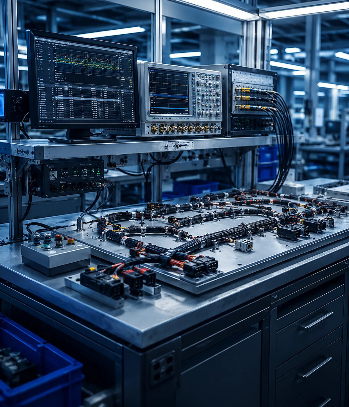
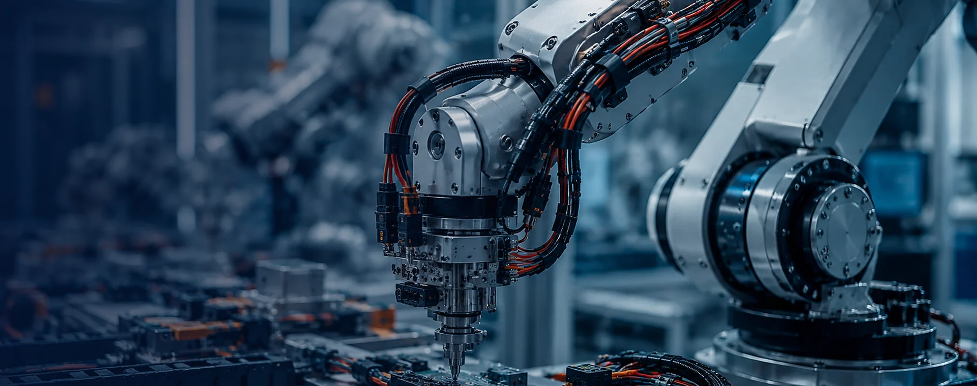
Premier Manufacturer
ISO9001:2015 Certified
IATF16949: Compliant
Robotics wiring harnesses for industrial robot motion signal and power connections
Robotics and Automation Connectivity

Robotics Wiring Harnesses for Motion, Signal and Power Reliability

JowChain develops robotics wiring harnesses for industrial robot arms, motors, encoders, sensors, controllers, charging interfaces and automated equipment. Designs can be customized for repeated motion, torsion, high temperature, compact routing and mixed power and signal requirements.

High-Flex Options Cable construction selected by movement and cycle requirements.
PTFE and Silicone Material options for heat, flexibility and demanding environments.
Custom Pin Counts 8-pin, 9-pin and project-specific connector interfaces.
Power and Signal Combined or separated circuit configurations.
Robot Arm Motion Harnesses for joints, motors, encoders and sensors.
Signal Connectivity Stable pin mapping for controls and feedback circuits.
Charging and Power Connections for mobile robots and charging interfaces.
Compact Integration Straight-to-angled and internal or external routing options.
Solution Overview

Robotics Harnesses Must Be Designed Around Motion, Not Only Electrical Load

Quick Summary

JowChain robotics wiring harnesses support power and signal transmission in industrial robots, robotic arms and automated equipment. Options include signal harnesses, PTFE high-temperature harnesses, combined power and signal assemblies, charging interfaces and custom 8-pin or 9-pin robot-arm connections.

A stationary harness may pass an electrical test and still fail quickly when installed through a moving robot joint. Repeated bending, torsion, acceleration, anchoring and cable-chain routing change the mechanical requirements.

JowChain reviews movement path, cycle expectation, bend radius, connector position, signal type and service method before confirming the cable construction.

Repeated-Motion Design

Cable construction is selected by bending, torsion, travel distance and cycle requirements.

Signal and Feedback Stability

Shielding and twisted pairs can support encoders, sensors and communication circuits.

Compact Connector Geometry

Straight, angled and custom pin-count interfaces support restricted installation space.

Service-Friendly Integration

Labels and replaceable sections can simplify robot maintenance.

JowChain engineering review for a custom robotics wiring harness
Solution Types

Robotics and Automation Connectivity Options

These solution directions are starting points. Final harness construction should follow the approved circuit architecture, installation drawing, connector list and validation plan.
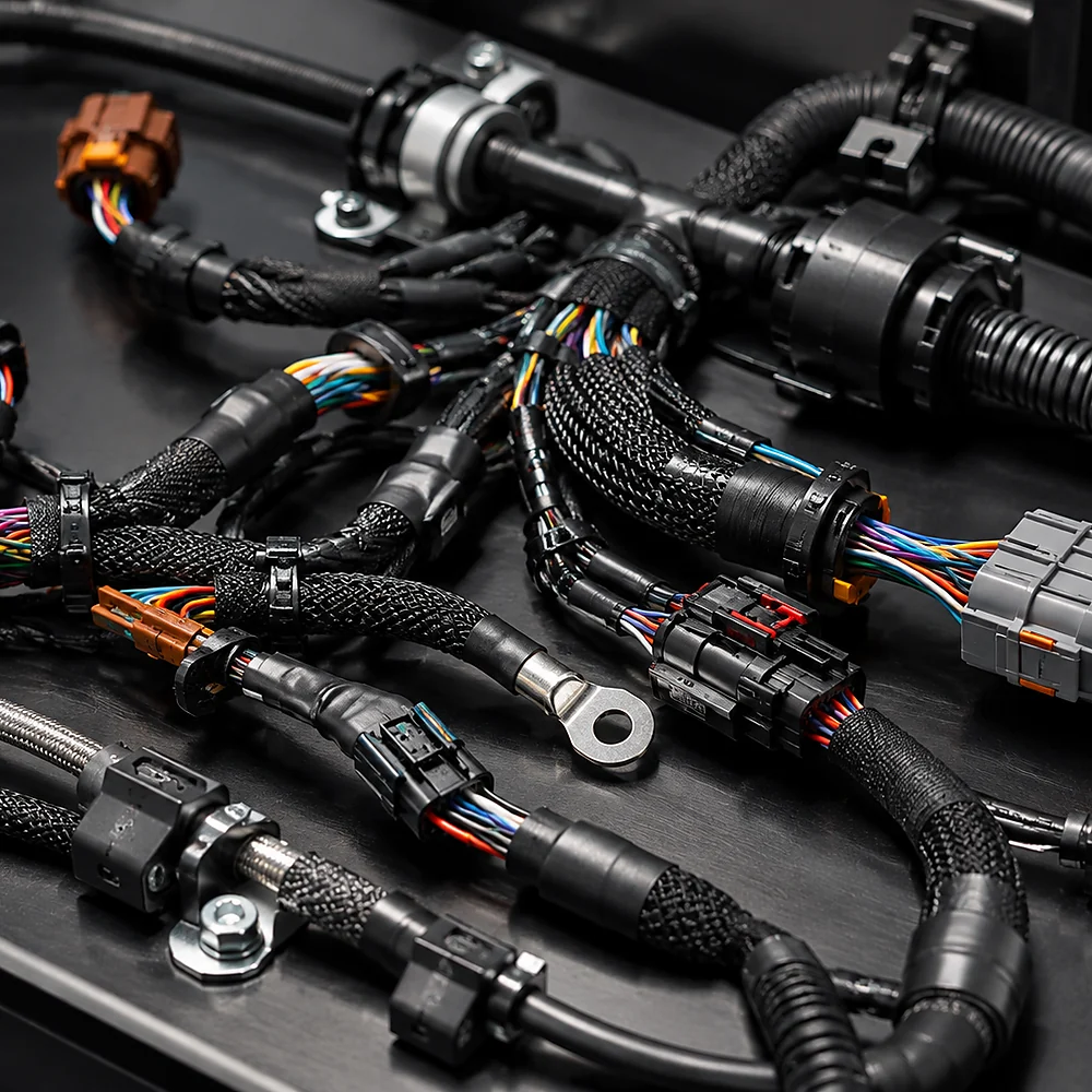
Signal connection harness for industrial robots

Signal Connection Harness

Connects sensors, encoders and control components where stable communication and accurate pin mapping are required.
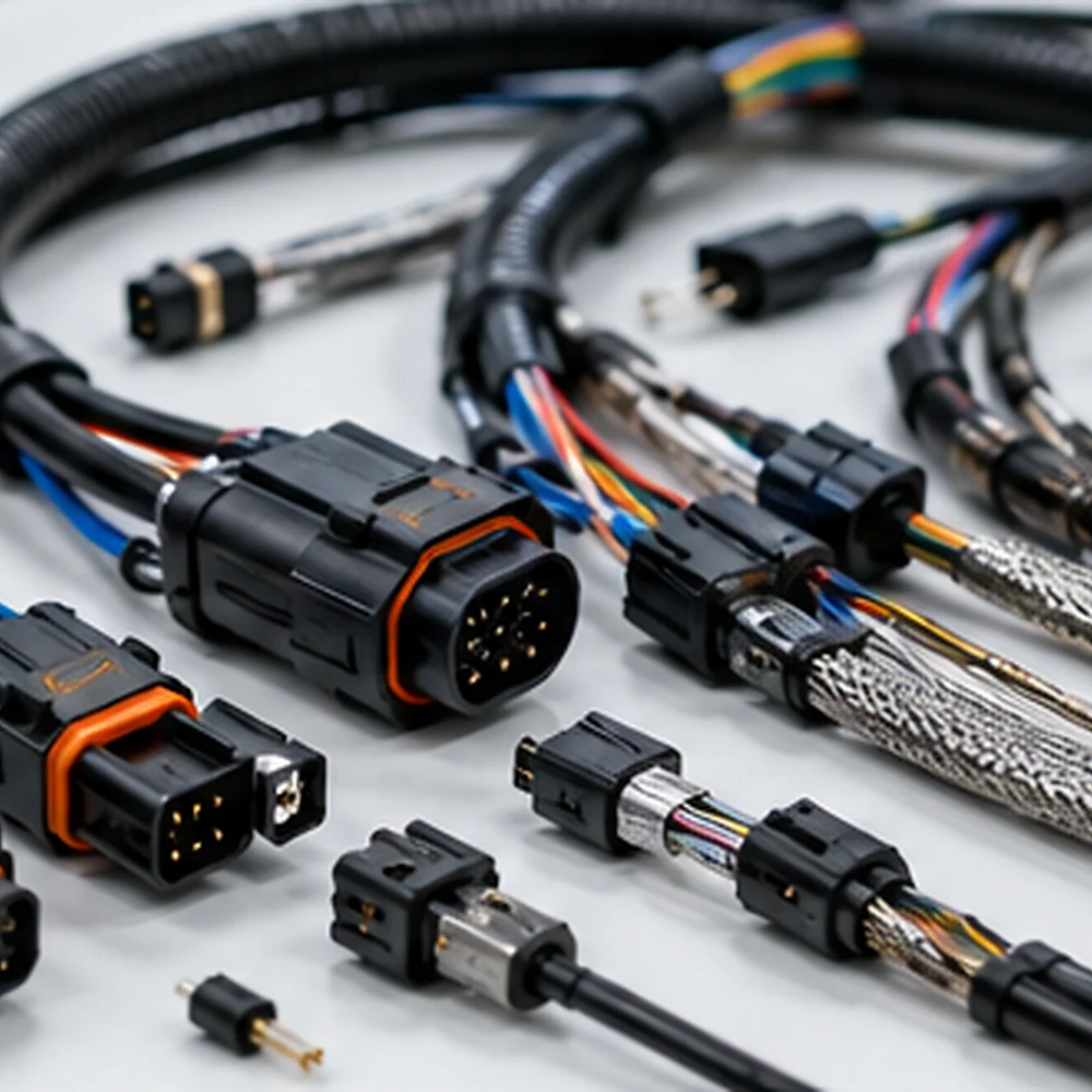
PTFE high-temperature robotics wiring harness

PTFE High-Temperature Harness

Uses PTFE or other suitable insulation for heat exposure and demanding robot environments.
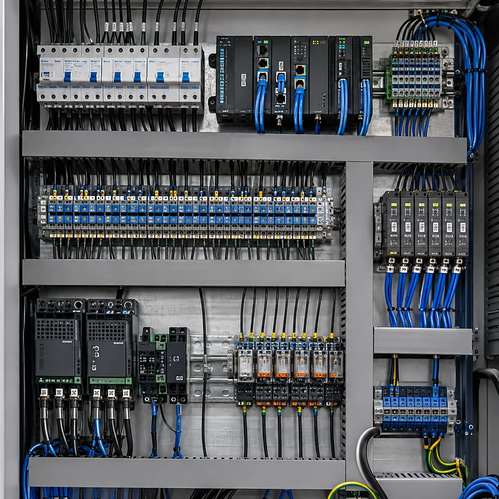
Combined robot power and signal wiring harness

Power and Signal Combination Harness

Combines power and control circuits when electrical separation, shielding and routing are properly reviewed.

Robot arm and charging interface cable assembly

Robot Arm and Charging Interface Harness

Custom 8-pin, 9-pin, angled or charging-interface assemblies for robot arms and mobile systems.

Technical Reference

Configurable Specifications and Engineering Boundaries

Final ratings must be confirmed against conductor size, terminals, connectors, ambient temperature, cable length and required validation conditions.

Parameter Available Direction
Conductor Copper, fine-strand or flexible construction selected by movement and electrical load.
Insulation PTFE, silicone, PVC or high-flex cable materials.
Circuit Type Signal, power, communication, charging or mixed circuits.
Connector Configuration Straight, angled, 8-pin, 9-pin, circular, rectangular or customer-specified.
Motion Requirement Stationary, repeated bending, torsion, drag-chain or articulated routing.
Temperature Defined by the selected cable and installation environment.
Protection Braided sleeve, corrugated tube, abrasion protection, strain relief or overmolding.
Identification Wire colors, labels, joint or axis IDs and connector markers.
Testing Continuity, pin mapping, dimensions, shield checks and project-specific motion validation.

Reference directions are not universal guarantees. Confirm the approved drawing, component data and operating conditions before quotation.

Applications

Where Robotics Wiring Harnesses Are Used

Harness construction changes with equipment architecture, circuit function, movement, environment and installation method.

Industrial robot arm wiring harness application

Industrial Robot Arms

Harnesses routed through articulated joints for motors, encoders, sensors and end effectors.
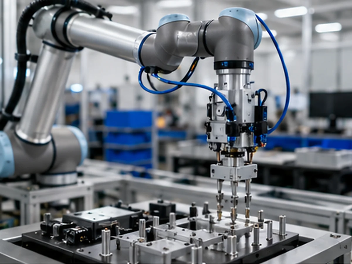
Collaborative and assembly robot wiring harness

Collaborative and Assembly Robots

Compact power and signal assemblies for limited space and serviceable modular connections.
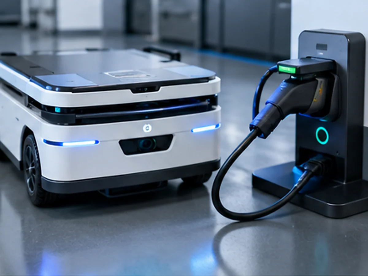
Mobile robot charging interface wiring harness

Mobile Robots and Charging Interfaces

Power, communication and charging harnesses for AGVs, AMRs and mobile robotic equipment.
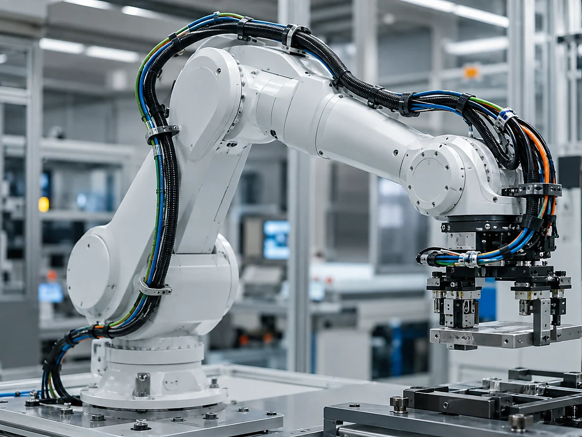
Automated machine and robotic end effector wiring harness

Automated Machines and End Effectors

Cable assemblies connecting grippers, vision systems, sensors, actuators and tool-change interfaces.
Failure Risks

Common Design Mistakes and Their Consequences

A harness can look correct on a workbench and still fail after installation. These risks should be reviewed before the drawing and BOM are released.

If ordinary cable is used for repeated bending

Conductors or shielding can fatigue even when the initial electrical test passes.

If bend radius is tighter than the cable design

Jacket damage and conductor stress can reduce cycle life.

If anchoring is placed at the moving point

The terminal or connector may carry mechanical load and fail prematurely.

If power and encoder signals are routed without review

Electrical noise can reduce control stability or feedback accuracy.

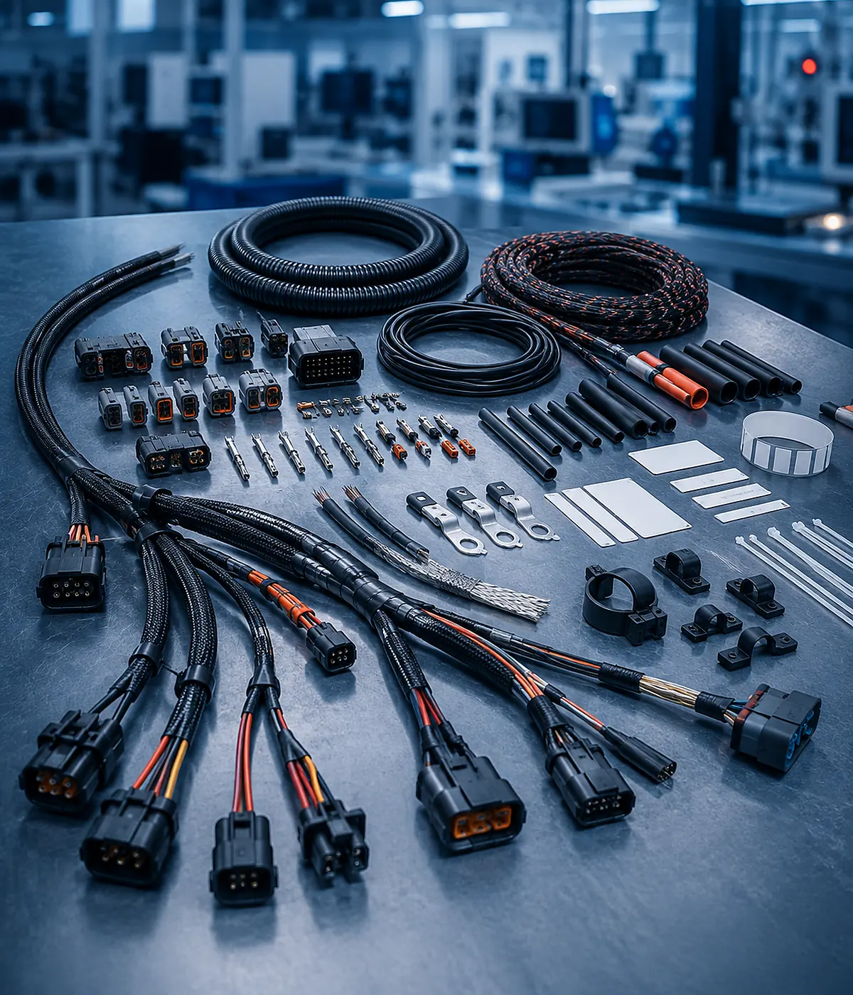
Custom components and protection options for robotics wiring harnesses
Customization

Engineering Options for the Approved Harness Design

Customization should be tied to a measurable requirement. Changing materials or connectors without understanding the electrical and mechanical consequences can create a cheaper BOM but a less reliable robotic system.

Cable Construction Fine-strand, high-flex, torsion-rated, PTFE, silicone or application-specific cable.
Connector Interface Straight, angled, 8-pin, 9-pin, circular, rectangular and customer-specified connectors.
Circuit Arrangement Motor power, brake, encoder, sensor, communication, charging and mixed circuits.
Mechanical Protection Drag-chain jacket, braided sleeve, strain relief, abrasion protection and overmolding.
Routing Axis-specific lengths, internal transitions, service loops and joint clearances.
Documentation Pin map, axis labels, motion condition, drawing revision and test plan.
Manufacturing Process

From Project Input to Controlled Production

The process identifies missing information early, verifies the prototype and reduces differences between the approved sample and repeat production.

01

Submit Requirements

Drawing, BOM, sample, application, quantity and test requirements.

02

Engineering Review

Review electrical load, movement, connectors and routing risks.

03

Component Confirmation

Confirm wires, terminals, housings, protection and alternatives.

04

Prototype Build

Create samples for fit, routing, pin mapping and verification.

05

First-Article Approval

Lock the drawing revision, BOM and acceptance criteria.

06

Production and Testing

Control assembly, inspection, records, packaging and delivery.

Quality and Validation

Testing Should Match the Actual Failure Risk

Electrical continuity is important, but it does not prove every mechanical or environmental requirement. JowChain aligns inspection and validation items with the project specification.

Electrical Continuity Confirms pin mapping and detects open or incorrect circuits.
Shield and Ground Check Verifies shield continuity and grounding for feedback or communication circuits.
Dimensional Inspection Checks axis lengths, branch positions, connector orientation and service loops.
Connector Retention Confirms terminal seating, locks and strain relief.
Static Bend and Fit Review Checks routing against robot geometry before motion testing.
Cycle or Motion Validation Project-specific movement testing can be planned when cycle life is critical.
Testing and validation for custom robotics wiring harnesses
Selection Logic

Choose the Harness by Operating Condition

Use these conditions as a purchasing shortcut. The final recommendation still requires circuit data, movement information and installation drawings.

Continuous bending in a cable chain Choose high-flex cable matched to bend radius, travel, speed and expected cycles.
Torsion through a rotating joint Choose torsion-capable cable rather than treating flex-only cable as equivalent.
Encoder signals near motor power Use suitable circuit separation, twisted pairs or shielding and define the grounding method.
Limited space at the robot joint Use angled connectors, compact breakouts and controlled service loops.
Frequent maintenance or tool changes Use labeled modular interfaces that can be replaced without disturbing the full robot harness.
Robotic arm wiring harness for repeated joint movement
Project Insight

Robotic Arm Harness for Repeated Joint Movement and Sensor Feedback

An industrial arm required motor power, encoder feedback and sensor connections through several moving axes. A standard cable bundle would have created excessive bend stress and made maintenance difficult.

  • Separated motor power from sensitive feedback circuits.
  • Defined minimum bend radius and service loops by axis.
  • Used compact angled connectors at restricted joints.
  • Added axis labels and modular connection points.
  • Planned fit verification before cycle validation.
Frequently Asked Questions

Buyer Questions About Robotics Wiring Harnesses

These answers focus on motion requirements, customization, testing and quotation preparation.

Provide the robot layout, movement path, bend radius, torsion angle, expected cycles, cable-chain dimensions, voltage and current, signal type, connectors, lengths and required tests.
High-flex or motion-oriented cable constructions can be reviewed. The correct choice depends on repeated bending, torsion, drag-chain travel or combined movement.
They can be combined when conductor separation, shielding, grounding and mechanical routing are reviewed. Separate branches may provide better signal integrity and easier maintenance.
Yes. Straight-to-angled 8-pin, industrial robot-arm 9-pin and other custom pin-count connector systems can be reviewed from drawings or samples.
PTFE, silicone, PVC and high-flex cable materials may be considered. Selection depends on temperature, flexibility, chemicals, abrasion and movement.
Electrical and dimensional inspection confirms the manufactured harness. Actual motion life should be validated under the intended bend radius, travel, speed, torsion and anchoring conditions.
Request a Quote

Send Your Drawing, BOM or Sample

Include the application, quantity, voltage and current, routing conditions, connectors and required validation. Complete inputs produce a more accurate recommendation.

Get A Quote