
Premier Manufacturer
ISO9001:2015 Certified
IATF16949: Compliant

CUSTOM BMS SIGNAL HARNESS MANUFACTURING

BMS Signal Wiring Harness

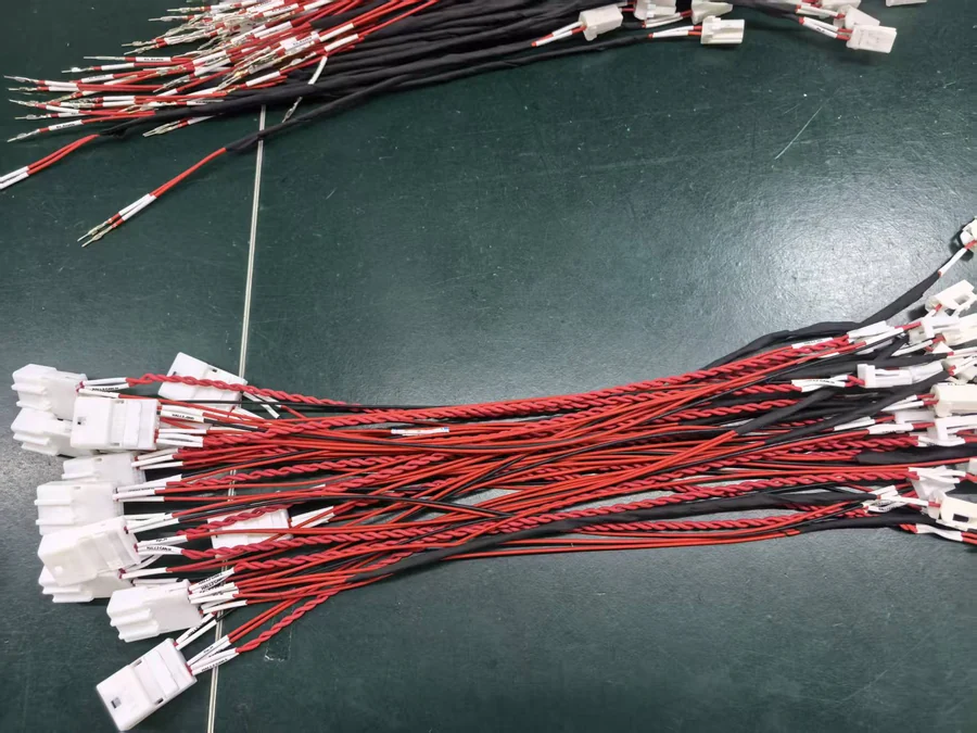
Custom BMS signal wiring harnesses manufactured to your drawing, BOM, connector pinout and circuit requirements. Configure signal wires, paired circuits, branch lengths, connector housings, terminals, labels and protection for battery management system sensing and control connections.
Drawing / BOM based production
Custom connector pinouts
Signal & sensing circuits
Branch labels & identification
BMS signal wiring harness manufacturer China JOWCHAIN
Actual BMS Signal Harness Signal wires + connector branches + circuit identification
01

Signal Wires

Wire specification selected according to drawing and circuit requirements.

02

Connector Pinout

Circuit-to-pin relationships controlled by the approved pin assignment.

03

Branch Layout

Individual leads and branches routed toward defined BMS connection points.

04

Identification

Labels and markers used to distinguish similar sensing circuits.

05

Protection

Sleeve, heat shrink or wrapping according to routing requirements.

Quick Buyer Summary:

A BMS signal wiring harness carries sensing, monitoring and control connections between battery-management components using defined wires, connector pinouts, branches and circuit identification. For accurate quotation, provide the wiring diagram or harness drawing, connector part numbers, pin assignment, branch dimensions and BOM.

PRODUCT OVERVIEW

Keep BMS Signal Circuits Organized, Identified and Repeatable

A BMS signal wiring harness organizes multiple low-current sensing and control circuits into one defined assembly. The harness can include separate wires, paired circuits, connector branches and identification labels according to the approved wiring diagram and connector pinout.

JOWCHAIN manufactures BMS signal harnesses from drawings, BOMs and confirmed component data. Connector housings, crimp contacts, wire specifications, branch dimensions, circuit labels and protection can be controlled to match the released design.

If your project also includes battery-pack power connections, cabinet interconnection or broader system routing, see our energy storage wiring harness solution for system-level harness planning.
Circuit Type Signal, sensing and control connections
Connector Project-specified housing and crimp contact
Pin Assignment Controlled according to approved circuit documentation
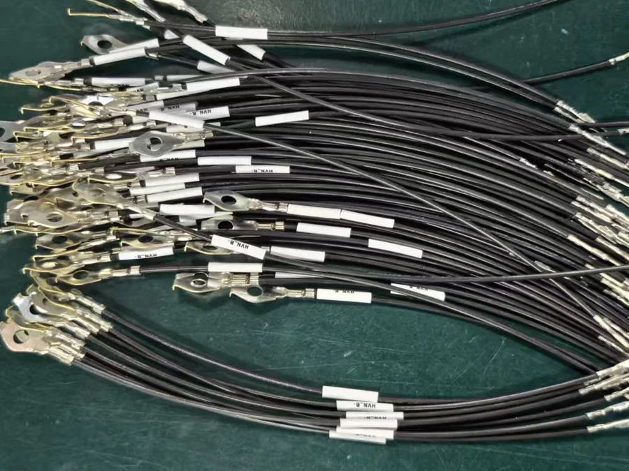
Identification Wire labels and circuit markers where required
BMS signal wiring harness wire identification and label detail

SIGNAL CIRCUIT CONFIGURATION

Define the Circuit Relationship Before Finalizing the Harness Layout

For a BMS signal harness, wire routing is only one part of the design. Each signal must also be assigned to the correct connector position, branch and identification reference.

1

Confirm Signal Functions

Identify each sensing or control circuit according to the approved electrical documentation.

2

Define Connector Pinout

Match individual circuits with the correct terminal and connector cavity.

3

Set Branch Dimensions

Control lead lengths and branch positions according to equipment routing.

4

Apply Identification

Use labels or markers where similar circuits need clear installation identification.

TECHNICAL SPECIFICATIONS

BMS Signal Harness Parameters Confirmed by Drawing and Pinout

Final configuration depends on the approved BMS circuit design, connector system and routing requirements rather than a fixed catalog specification.

Signal Wire Gauge, insulation and color according to approved BOM
Paired Circuits Twisted or paired configuration where specified by project documentation
Connector Housing Project-specified BMS connector and mating interface
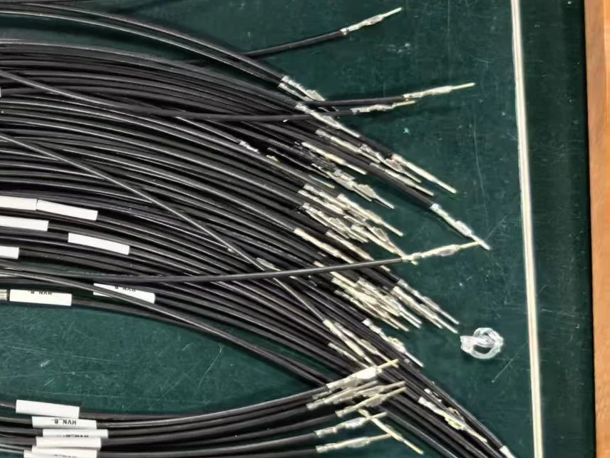
Crimp Contact Terminal part number matched to connector and wire range
Pin Assignment Controlled according to released circuit and connector documentation
Branch Length Customized according to installation routing
Identification Wire labels, markers or circuit coding where required
Protection Heat shrink, sleeve, wrapping or specified local protection
Production Basis Approved drawing, BOM, pinout and inspection requirements
BMS signal wiring harness crimp contact and pin detail

CONNECTOR & PINOUT CONTROL

A Correct Wire Is Useless If It Enters the Wrong Connector Position

BMS signal harness quality depends heavily on connector assignment and circuit position. Similar wires or repeated connector cavities can create mistakes if the released pinout is not followed consistently.

If your project only requires simple pre-terminated leads rather than a complete BMS signal assembly, our custom terminal lead wire harness may be a more appropriate product structure.

Connector Part Number Confirm the correct housing and mating interface.
Crimp Contact Match the contact to the specified wire and connector cavity.
Pin Assignment Follow released circuit-to-pin documentation.
Circuit Identification Label similar leads when installation identification is required.

BUYER SELECTION GUIDE

Choose the Harness Structure From the Circuit Architecture

The right product structure depends on whether you need individual signal leads, several simple branches or a defined BMS connector and pinout assembly.

IF YOU NEED

Individual Pre-Terminated Leads

Use separate wire leads when each connection can be handled independently.

→ Choose Custom Terminal Lead Wire Harness.
IF YOU NEED

Multiple Physical Branches

Use a structured branch harness when routing geometry is the main design requirement.

→ Choose Custom Multi-Branch Wire Harness.
IF YOU NEED

Defined BMS Signal & Pinout Circuits

Use a BMS signal harness when circuit assignment and connector pin positions must be controlled together.

→ Choose BMS Signal Wiring Harness.

RFQ CHECKLIST

What Should You Send for a BMS Signal Harness Quote?

BMS signal harness quotation depends on more than wire length. Connector assignments and circuit documentation are equally important.

Recommendation: send the harness drawing and connector pinout together. A drawing without pin assignment can still leave important electrical relationships unclear.
01 Harness Drawing Branch dimensions, connector positions and overall routing.
02 Wire BOM Wire specification, color and circuit identification.
03 Connector List Housing and terminal part numbers.
04 Pinout Signal-to-pin relationship for each connector.
05 Protection Heat shrink, sleeve or wrapping requirements.
06 Quantity Prototype, pilot and expected production quantities.

COMMON SPECIFICATION MISTAKES

Four BMS Harness Errors That Can Be Difficult to Find After Assembly

BMS signal harness problems often come from circuit assignment rather than visible wire damage. Clear documentation reduces the risk before production begins.

Incorrect Pin Assignment

The correct wire installed in the wrong connector cavity still creates an incorrect circuit.

Consequence: sensing or control signal mismatch.

Missing Circuit Labels

Similar signal wires become difficult to identify during installation or inspection.

Consequence: slower assembly and troubleshooting.

Wrong Branch Length

A short signal branch may not reach the intended BMS connection point.

Consequence: routing tension or installation failure.

Connector Part Mismatch

Similar housings or contacts may not match the intended mating interface.

Consequence: mating, retention or assembly problems.

PRODUCTION & QUALITY CONTROL

Verify Circuit Relationships, Not Only Harness Dimensions

BMS signal harness inspection should confirm connector components, branch dimensions, circuit-to-pin relationships and identification against the released drawing and electrical documentation.

01

Component Verification

Wires, connectors and contacts are checked against the approved BOM.

02

Branch Dimension Check

Lead lengths and connector positions are verified against drawing dimensions.

03

Circuit Verification

Signal and connector relationships can be checked against the approved pinout.

04

Final Identification

Wire markers, labels and connector assignments are checked before packing.

ISO 9001 ISO 14001 QC08000 IATF 16949 UL Wire Harness

FAQ

BMS Signal Wiring Harness FAQs

Yes. Drawing, BOM and connector pinout information are the preferred production basis because they define the wire specification, connector components, branch dimensions and circuit relationships.

Yes. Connector cavities and signal circuits can be assembled according to the approved pinout and wiring documentation.

Yes. Wire gauge, insulation, color, branch length and paired or twisted configurations can be produced where specified by the approved design.

Yes. Circuit labels, wire markers and branch identification can be added according to assembly and inspection requirements.

Provide the harness drawing, wire BOM, connector and terminal part numbers, pin assignment, branch dimensions, protection requirements and expected production quantity.

REQUEST A CUSTOM QUOTE

Need a BMS Signal Harness Built to Your Pinout?

Send your harness drawing, BOM, connector list and pin assignment to JOWCHAIN for technical review and quotation. Confirming circuit relationships and branch dimensions before production helps reduce wiring errors and unnecessary rework.

Get A Quote