Premier Manufacturer
ISO9001:2015 Certified
IATF16949: Compliant
Energy storage wiring harnesses for battery power BMS and cabinet integration
Battery and ESS Connectivity

Energy Storage Wiring Harnesses for Power, BMS and Cabinet Integration

JowChain supplies energy storage wiring harnesses for battery modules, pack junction boxes, BMS collection, temperature sensing, high-voltage power distribution and cabinet interconnection. Configurations can be adapted to voltage, current, installation space, insulation and maintenance needs.

12V–800V Configurable reference range subject to component validation.
Up to 400A Reference direction for suitable power harness assemblies.
-40°C to 125°C Material-dependent operating temperature reference.
Custom Layouts Straight, angled, split and long-distance configurations.
Battery Pack Power High-current links between modules, junction boxes and converters.
BMS Collection Cell-voltage, temperature and communication harnesses.
Cabinet Interconnection Organized power and signal routing for ESS cabinets.
Renewable Integration Harnesses for batteries, inverters and renewable-energy interfaces.
Solution Overview

Energy Storage Systems Need Clear Separation of Power, Sensing and Communication Circuits

Quick Summary

JowChain energy storage wiring harnesses support power transmission, BMS data collection, temperature sensing and cabinet interconnection. Options include battery-pack high-voltage harnesses, silicone-insulated assemblies, angled connectors, protected cables, BMS collection harnesses and multi-branch power distribution.

An energy storage cabinet may contain high-current power cables, cell-voltage collection, temperature sensors, communication circuits and auxiliary power. Poor routing or unclear identification increases polarity risk, installation time and maintenance difficulty.

JowChain reviews the pack and cabinet architecture before defining conductor size, connector orientation, branch layout, labels, insulation and protection.

Power Circuit Control

Conductors, terminals and insulation are selected around current, voltage drop and thermal conditions.

BMS Channel Organization

Cell and temperature circuits can be grouped and labeled according to the approved BMS map.

Cabinet-Space Optimization

Straight, angled and split configurations support restricted space and service access.

Protection and Identification

Sleeves, tubes, heat-shrink and labels can be added according to location and risk.
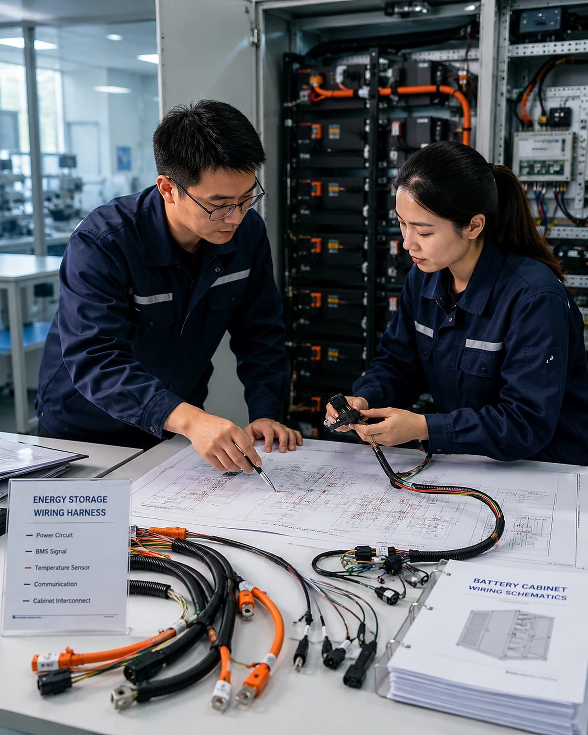
JowChain engineering review for an energy storage wiring harness
Solution Types

Battery and ESS Connectivity Product and Circuit Options

These solution directions are starting points. Final harness construction should follow the approved electrical architecture, installation drawing, connector list and validation plan.
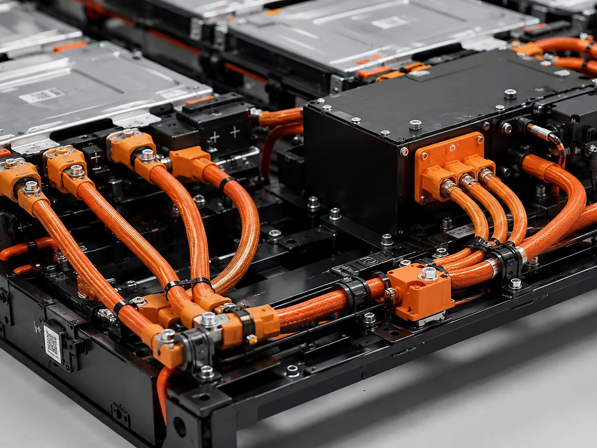
Battery pack high-voltage wiring harness

Battery Pack High-Voltage Harness

Power connections for battery modules, junction boxes, contactors, fuses and inverter interfaces.
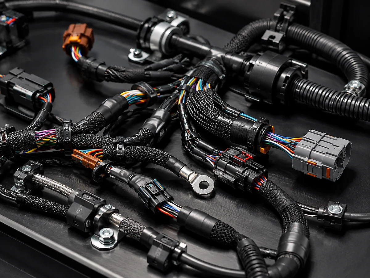
Battery management system collection wiring harness

BMS Collection Harness

Organized cell-voltage, temperature and communication circuits for battery-management systems.
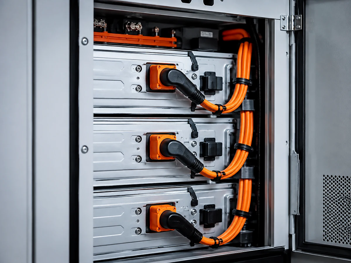
Angled energy storage wiring harness for compact cabinets

Angled and Space-Saving Harness

90-degree or customized connector exits for compact cabinets and restricted installation zones.
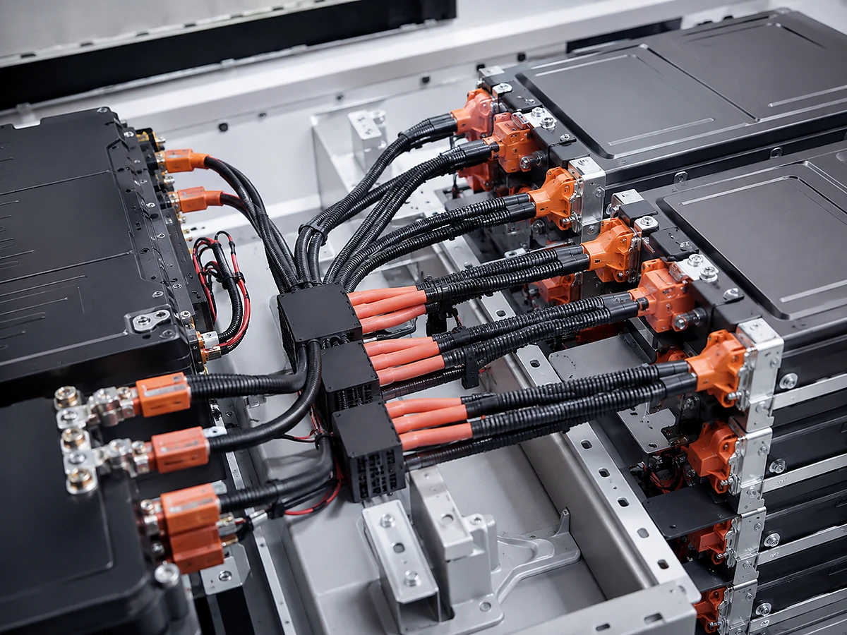
Multi-branch energy storage power wiring harness

Multi-Branch Power Harness

One-to-many or distribution configurations for cabinet modules and parallel connection points.

Technical Reference

Configurable Specifications and Engineering Boundaries

Final ratings must be confirmed against conductor size, terminals, connectors, ambient temperature, cable length and required validation conditions.

Parameter Available Direction
Conductor High-conductivity copper selected by current, voltage drop and thermal load.
Voltage Reference 12V to 800V reference range; project-specific component and insulation validation required.
Current Reference Up to 400A reference for suitable power harness configurations.
Wire Gauge Reference 18 AWG to 6 AWG reference; larger or alternative conductor sizes can be reviewed.
Temperature Reference -40°C to 125°C depending on selected materials and components.
Insulation PVC, PTFE, silicone and project-approved protective materials.
Connector Layout Straight, angled, box-mounted, split or customer-specified.
Protection Fiberglass tube, corrugated tube, braided sleeve, heat-shrink and abrasion protection.
Testing Continuity, polarity, insulation, high-voltage, dimensional and project-specific validation.

Reference values are not universal guarantees. Confirm the approved drawing, component data and operating conditions before quotation.

Applications

Where Energy Storage Wiring Harnesses Are Used

Harness construction changes with equipment architecture, circuit function, installation environment and cabinet layout.
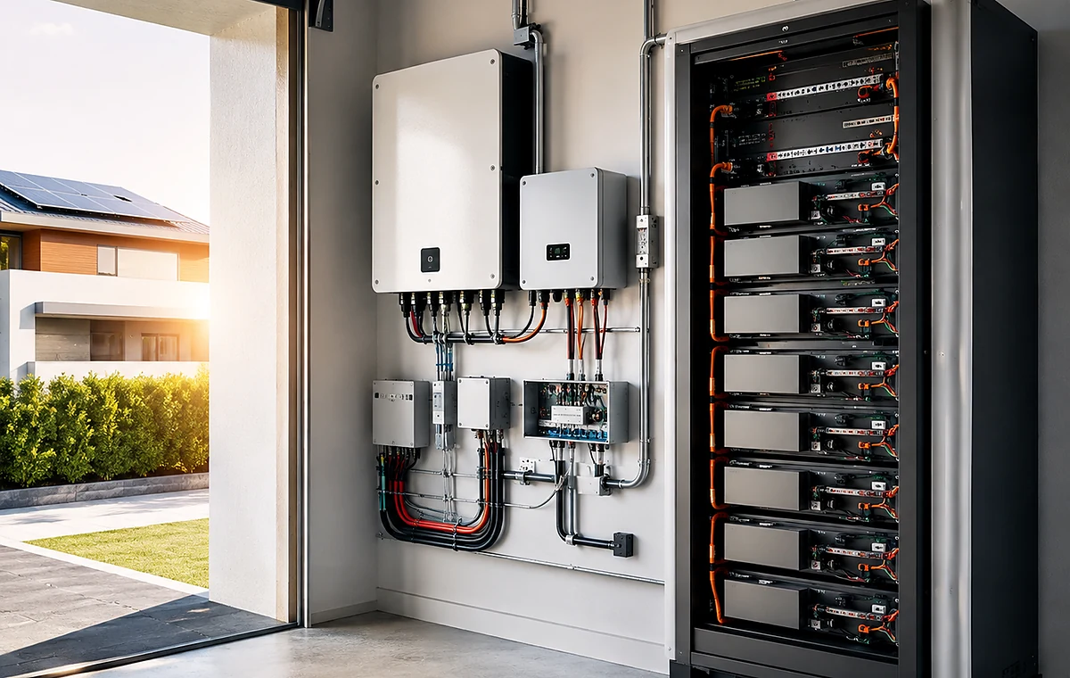
Residential and commercial energy storage wiring harness

Residential and Commercial ESS

Power and BMS harnesses connecting battery modules, inverters, controls and cabinet interfaces.
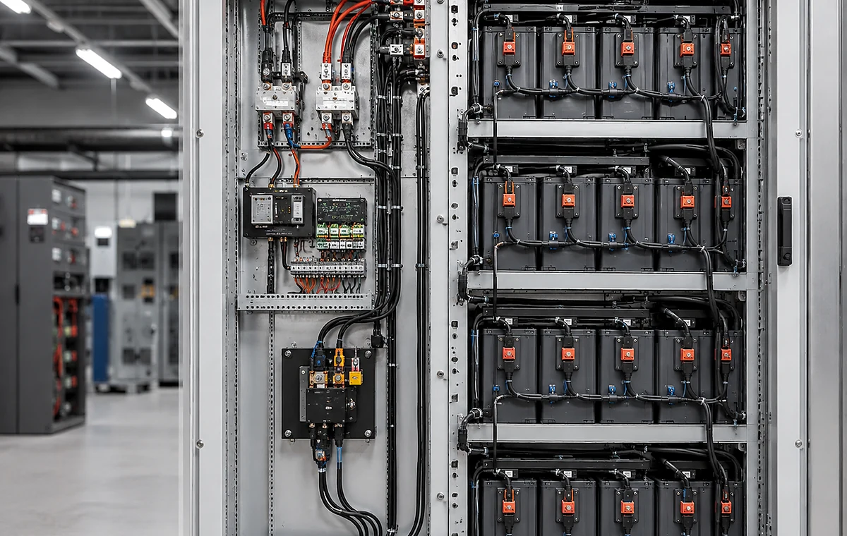
Industrial battery cabinet wiring harness

Industrial Battery Cabinets

Long or multi-branch harnesses designed around cabinet layout, service access and installation order.
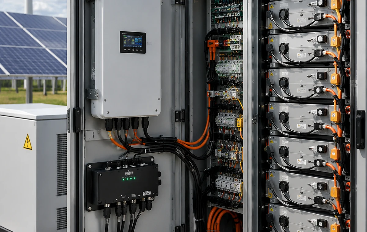
Renewable energy storage wiring harness system

Renewable Energy Storage

Connections between batteries, converters, monitoring devices and renewable-energy interfaces.
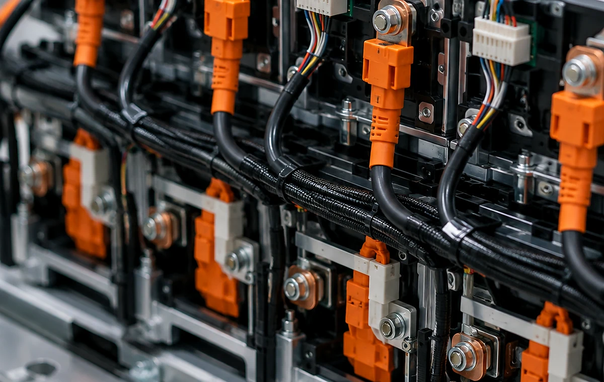
Battery module and pack assembly wiring harness

Battery Module and Pack Assembly

Module-level voltage collection, temperature sensing and pack-level power distribution.
Failure Risks

Common Design Mistakes and Their Consequences

A harness can appear correct before installation and still create commissioning, thermal or maintenance problems inside the battery cabinet.

If polarity and labels are unclear

Installation mistakes can damage modules or delay cabinet commissioning.

If high-current cable length is underestimated

Voltage drop, heat and routing stress may exceed the design expectation.

If power and BMS circuits lack structure

Maintenance becomes harder and signal faults are more difficult to isolate.

If angled exits are not checked against the cabinet

Cables or connectors may interfere with doors, busbars or adjacent modules.

Custom cable connectors and protection options for energy storage wiring harnesses
Customization

Engineering Options for the Approved Harness Design

Customization should be tied to a measurable electrical, mechanical or installation requirement. Component changes should be reviewed before the approved drawing and BOM are released.

Power Cable Conductor size, insulation, lug or connector system, color and cable length.
BMS Harness Channel count, pin map, sensor branches, wire colors and labels.
Connector Geometry Straight, 90-degree, panel-mounted, box harness and custom breakout directions.
Protection Silicone insulation, fiberglass tube, corrugated tube, heat-shrink and abrasion sleeves.
Distribution Layout One-to-one, one-to-many, module-to-pack and cabinet interconnection structures.
Documentation Polarity map, BMS channel map, drawing revision, BOM and test instructions.
Manufacturing Process

From Project Input to Controlled Production

The process identifies missing information early, verifies the sample and reduces differences between the approved prototype and repeat production.

01

Submit Requirements

Drawing, BOM, sample, application, quantity and required tests.

02

Engineering Review

Review electrical load, connectors, routing and manufacturing risks.

03

Component Confirmation

Confirm wires, terminals, housings, sleeves, labels and alternatives.

04

Prototype Build

Create samples for fit, routing, pin mapping and verification.

05

First-Article Approval

Lock the drawing revision, BOM and acceptance criteria.

06

Production and Testing

Control assembly, inspection, records, packaging and delivery.

Quality and Validation

Testing Should Match the Actual Failure Risk

Electrical continuity is important, but it does not prove every mechanical, thermal or installation requirement. Validation items should follow the approved project specification.

Continuity and Polarity Confirms the correct circuit and polarity before installation into the battery system.
Insulation and High-Voltage Test Applied to power harnesses where required by the approved validation plan.
Crimp and Terminal Verification Pull force, crimp height or cross-section inspection can be selected by terminal risk.
Dimensional Inspection Confirms cable length, branch position and angled exits against the cabinet drawing.
Label and Channel Check Verifies BMS channel identification and module labels.
First-Article Approval Confirms the sample, drawing revision and test standard before repeat production.
Testing and validation of an energy storage wiring harness
Selection Logic

Choose the Harness by Operating Condition

Use these conditions as a purchasing shortcut. The final recommendation still requires circuit data, installation drawings and cabinet operating conditions.

Battery module to junction box Choose a power harness sized for current, cable length and expected temperature rise.
Cell-voltage and temperature monitoring Choose a BMS collection harness with controlled pin mapping and channel identification.
Restricted cabinet depth Use angled connectors or planned cable exits to avoid sharp bends and door interference.
Multiple parallel modules Use a multi-branch layout with clear polarity and module identification.
Long-distance cabinet connection Review conductor size and voltage drop rather than extending the existing specification without validation.
Commercial battery cabinet with separate power and BMS wiring harnesses
Project Insight

Battery Cabinet with Separate Power and BMS Harness Architecture

A commercial storage cabinet required high-current module connections, BMS voltage collection and temperature sensing. The project needed clear separation of circuit types while preserving service access inside a narrow cabinet.

  • Separated power, sensing and communication branches.
  • Added module and polarity identification.
  • Used angled exits where cabinet depth was restricted.
  • Reviewed long cable sections for voltage drop and routing.
  • Confirmed BMS channel mapping before pilot assembly.
Frequently Asked Questions

Buyer Questions About Energy Storage Wiring Harnesses

These answers focus on specifications, customization, installation control and quotation preparation.

JowChain can support battery-pack high-voltage harnesses, BMS collection harnesses, temperature-sensor harnesses, angled cable assemblies, long-distance cabinet harnesses, protected cable assemblies and multi-branch power layouts.
The current JowChain page references 12V to 800V and up to 400A for suitable configurations. Final ratings depend on conductor size, terminal system, cable length, temperature and validation requirements.
Yes. Provide the BMS pin map, cell count, sensor positions, connector list and labeling requirements. Channel identification should be confirmed before sample production.
Yes. Angled connectors and customized breakout directions can reduce cable stress in compact cabinets, but the exit direction should be confirmed against the cabinet model.
Polarity maps, color coding, connector keying, module labels, first-article inspection and electrical continuity or polarity testing can be included in the project plan.
Yes. The harness can connect battery modules, inverters, monitoring devices and other storage-system components when the electrical and environmental requirements are clearly specified.
Request a Quote

Send Your Drawing, BOM or Sample

Include the application, quantity, voltage and current, routing conditions, connector list and required validation. Complete inputs produce a more accurate recommendation.

Get A Quote