
Wire Harness Technical Articles and Engineering Guide
A practical guide for engineering buyers, product developers and sourcing teams evaluating custom wire harness requirements, components, manufacturing processes, testing and repeat production.
Quick Summary
A wire harness is not only a group of wires and connectors. It is an electrical and mechanical connection system that must fit the equipment, withstand the operating environment and remain repeatable in production.
Why a Wire Harness Engineering Guide Matters
The difficult part of purchasing a custom wire harness is rarely finding a supplier that can cut wire and install terminals. The difficult part is confirming whether the complete design will carry the required electrical load, fit the equipment, survive movement and environmental exposure, pass the correct tests and remain stable in repeat production.
Many project problems appear because one part of the decision chain is treated separately. A connector may match electrically but be difficult to install. A wire gauge may carry the nominal current but create excessive voltage drop over the full circuit length. A hand-adjusted sample may fit once but cannot be reproduced consistently during batch assembly.
A practical technical guide should connect the full decision chain:
When these stages are disconnected, the result is often repeated sampling, terminal problems, routing conflicts, test failures or inconsistent repeat orders.
Complete Wire Harness Review Process
Use the following process before releasing a custom wire harness for production.
Clarify the Application
Define equipment type, circuit function, installation environment, movement and service conditions.
Confirm Electrical Requirements
Review current, voltage, conductor length, voltage drop, temperature and circuit protection.
Match Components
Confirm wire, terminal, connector, seal, protection, labeling and fastening materials.
Build and Review the Prototype
Check dimensions, branch direction, connector orientation, installation access and manufacturability.
Define Verification
Confirm crimp inspection, continuity, short-circuit, insulation, functional and environmental tests.
Release Production Standards
Freeze approved materials, drawings, work instructions, test points and revision controls.
Step 1 Clarify the Real Harness Requirements
Starting from connector part numbers or target price alone is not enough. The application determines which technical parameters should control the design.
| Key Question | Why It Matters | Technical Direction |
|---|---|---|
| What current and voltage will the circuit carry? | Controls conductor size, terminal capacity, heat generation and test requirements. | Review wire gauge, voltage drop and connector current rating. |
| Will the harness remain static or move repeatedly? | Changes conductor flexibility, bend radius, strain relief and protection needs. | Use flexible conductors and movement-compatible routing where required. |
| Will the harness face heat, oil, water or chemicals? | Determines insulation, sealing and outer protection materials. | Match material performance to the actual environment rather than general labels. |
| Is installation space limited? | Affects connector orientation, branch exits, service loops and assembly sequence. | Review the equipment layout before fixing harness dimensions. |
| Does the circuit carry sensitive signals? | Signal circuits may require shielding, twisting, separation or controlled grounding. | Confirm EMI conditions and signal protocol before selecting cable structure. |
Step 2 Confirm the Core Technical Parameters
Wire harness selection should be based on a group of connected parameters. Improving one parameter does not automatically improve the complete system.
| Parameter | Technical Impact | Common Risk |
|---|---|---|
| Wire Gauge | Controls current capacity, conductor resistance, voltage drop and terminal compatibility. | Oversizing creates cost and installation difficulty; undersizing creates heat and voltage loss. |
| Conductor Length | Affects resistance, voltage drop and final branch dimensions. | Nominal wire gauge may be insufficient when the circuit becomes longer. |
| Terminal Wire Range | Defines whether the conductor can be compressed correctly inside the terminal barrel. | Incorrect combinations cause low pull force, strand loss or high resistance. |
| Crimp Height | Controls conductor compression and the mechanical-electrical interface. | Over-crimping damages strands; under-crimping reduces retention and conductivity. |
| Bend Radius | Protects conductors and shielding from mechanical damage. | Sharp bends cause fatigue, deformation and premature failure. |
| Protection Material | Controls abrasion, heat, moisture, flexibility and installation behavior. | The strongest protection is not always the best for moving or compact applications. |
Do not approve a harness by checking only the drawing and pinout. Confirm how electrical load, mechanical routing, terminal termination and final testing work together.
Step 2 Confirm the Core Technical Parameters
Wire harness selection should be based on a group of connected parameters. Improving one parameter does not automatically improve the complete system.
| Parameter | Technical Impact | Common Risk |
|---|---|---|
| Wire Gauge | Controls current capacity, conductor resistance, voltage drop and terminal compatibility. | Oversizing creates cost and installation difficulty; undersizing creates heat and voltage loss. |
| Conductor Length | Affects resistance, voltage drop and final branch dimensions. | Nominal wire gauge may be insufficient when the circuit becomes longer. |
| Terminal Wire Range | Defines whether the conductor can be compressed correctly inside the terminal barrel. | Incorrect combinations cause low pull force, strand loss or high resistance. |
| Crimp Height | Controls conductor compression and the mechanical-electrical interface. | Over-crimping damages strands; under-crimping reduces retention and conductivity. |
| Bend Radius | Protects conductors and shielding from mechanical damage. | Sharp bends cause fatigue, deformation and premature failure. |
| Protection Material | Controls abrasion, heat, moisture, flexibility and installation behavior. | The strongest protection is not always the best for moving or compact applications. |
Do not approve a harness by checking only the drawing and pinout. Confirm how electrical load, mechanical routing, terminal termination and final testing work together.
Technical Selection Guide for Common Wire Harness Challenges
Use this guide to identify the technical priority behind common wire harness problems. Final decisions should still be verified against the actual equipment, drawings, components and test requirements.
| Common Project Challenge | Technical Priority | Additional Checks |
|---|---|---|
| Wire temperature or voltage loss | Conductor size, circuit length, current derating and terminal capacity. | Bundling, ambient temperature and contact resistance. |
| Connector cannot fit or be serviced | Orientation, locking space, mating access and branch exit direction. | Equipment installation sequence and maintenance access. |
| Crimp pull force is unstable | Strip length, conductor position, crimp height and tooling condition. | Wire-terminal compatibility and strand damage. |
| Harness fails during repeated movement | Flexible conductor, bend radius, strain relief and routing path. | Twisting, abrasion points and connector movement. |
| Signal circuit experiences interference | Shielding, twisted pair, circuit separation and grounding method. | Shield termination quality and connector interface. |
| Prototype passes but batch results vary | Controlled work instructions, fixtures, inspection points and revision control. | Manual adjustments that were never documented. |
Manufacturing and Technical Support
Wire harness cooperation does not end when the first sample is approved. The design must be transferred into repeatable manufacturing steps, inspection points and test methods.
| Stage | Support Content | Project Benefit |
|---|---|---|
| Requirement Review | Drawing, BOM, application and component review. | Fewer unsuitable samples and clearer quotation basis. |
| Prototype Stage | Sample build, dimensional review and connection verification. | Earlier identification of installation and assembly risks. |
| Process Preparation | Crimp settings, work instructions, fixtures and inspection controls. | More stable transfer from sample to production. |
| Batch Production | Controlled materials, process checks and electrical testing. | More predictable quality across repeat orders. |
| Engineering Change | Revision review, document updates and controlled implementation. | Reduced risk of mixed versions and undocumented substitutions. |
Quality Assurance and Repeat Supply Stability
One acceptable sample does not prove that every future harness will perform the same way. Repeat supply depends on controlled materials, documented processes, inspection standards, test fixtures and revision management.
What to Confirm Before Repeat Production
Approved BOM
Wire, terminals, connectors, seals, protection and labeling materials are clearly identified.
Controlled Drawings
Lengths, branches, pinout, orientation and special assembly details match the approved sample.
Process Standards
Cutting, stripping, crimping, assembly and inspection methods are documented.
Verification Criteria
Crimp, visual, dimensional and electrical checks have clear release conditions.
For repeat projects, confirm that future orders use the same approved technical basis unless an engineering change is reviewed and released.
Related Wire Harness Technical Articles
Use these article topics to move from general engineering logic to a specific design, manufacturing or testing question.
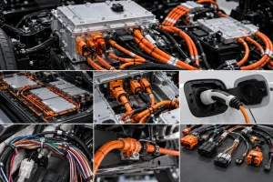
How to Select Cables Connectors and Protection for EV Wiring Harnesses
Learn how to select cables, connectors and protection for an Electric Vehicle Wiring Harness, including HV cable, HVIL, shielding, sealing, testing and supplier checks.
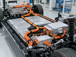
Electric Vehicle Wiring Harness Design for High Voltage Applications
Learn how to design an Electric Vehicle Wiring Harness for high voltage systems, including cable sizing, HV connectors, HVIL, shielding, testing and supplier checks.
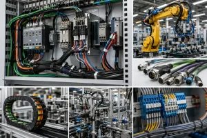
Industrial Wire Harness Design for Automation Equipment
Learn how to design an Industrial Wire Harness for automation equipment, including servo cables, encoder signals, sensors, drag chains, EMI control and supplier checks.
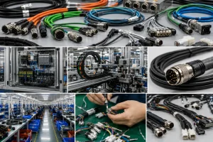
Custom Cable Assembly Design Guide for Industrial Equipment
Learn how to design a Custom Cable Assembly for industrial equipment, including connectors, shielding, drag chains, cable materials, testing and supplier checks.
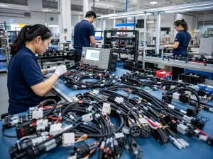
How to Choose a Wire Harness Manufacturer for Long Term OEM Supply
Learn how to choose a Wire Harness manufacturer for long-term OEM supply, including factory audits, testing, documentation, capacity, change control and supply risk.
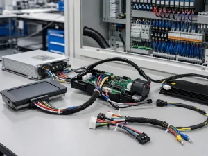
Electronic Wire Harness Design for Consumer and Industrial Electronics
Learn how to design an Electronic Wire Harness for consumer and industrial electronics, including PCB connectors, EMI shielding, testing, compliance and supplier checks.
Wire Harness Engineering FAQ
Provide the drawing, BOM, connector references, circuit voltage and current, installation environment, expected movement, quantity, sample requirements and any defined test standards.
No. Conductor length, voltage drop, ambient temperature, circuit bundling, duty cycle, terminal capacity and insulation requirements should also be considered.
Crimp height affects conductor compression, mechanical retention and electrical resistance. An incorrect crimp height can damage strands or create an unstable connection.
Shielding may be required when signal circuits are sensitive to electromagnetic interference or when the harness operates close to motors, switching devices, high-current cables or other noise sources.
Confirm the approved BOM, dimensions, branch layout, connector orientation, crimp requirements, inspection points, electrical tests and revision status.
Need Help Reviewing a Wire Harness Requirement?
Share the available project information so the technical requirements, component choices, prototype needs and verification path can be reviewed before unnecessary sampling or production risk appears.