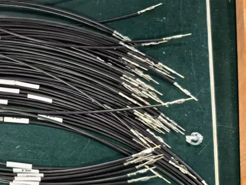
CUSTOM BMS CONNECTOR HARNESS MANUFACTURING
Custom BMS multi-connector wiring harnesses manufactured to your drawing, BOM, connector list and pin assignment. Configure multiple connector housings, individual branch lengths, wire specifications, circuit identification and protection within one controlled battery-management harness assembly.
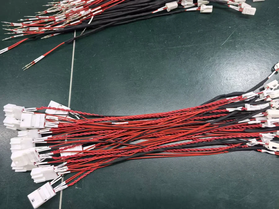
Define every housing and mating interface used in the assembly.
Map each circuit to the required connector cavity and contact.
Control breakout locations and individual connector branch lengths.
Labels and markers help distinguish similar connector branches.
Sleeve, tape or heat shrink can be specified by routing zone.
A BMS multi-connector wiring harness combines several connector interfaces into one organized battery-management assembly. Correct production depends on the connector list, terminal part numbers, pin assignment, branch dimensions and circuit identification being controlled together rather than specified separately.
PRODUCT OVERVIEW
A BMS multi-connector harness organizes several connector interfaces into one controlled assembly. Each connector branch can have its own housing, crimp contacts, pin assignment, branch length and identification while remaining part of the same released wiring harness.
JOWCHAIN manufactures these assemblies from approved drawings, BOMs and pinout information so connector identity, branch routing, circuit position and wire preparation remain repeatable from prototype through production.
If the project also includes battery-pack power connections, cabinet interconnection or broader routing requirements, review our energy storage wiring harness solution for system-level planning.
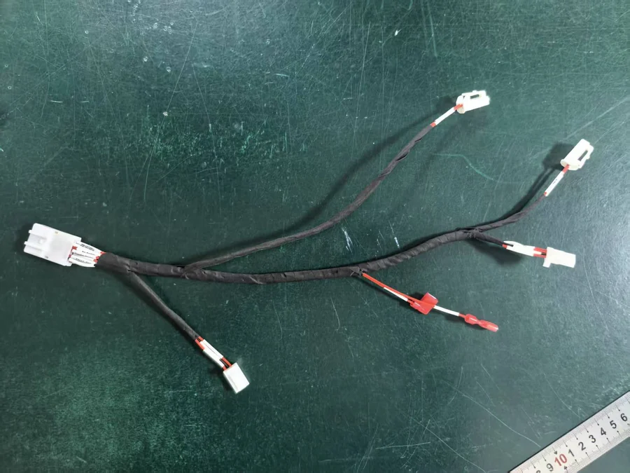
MULTI-CONNECTOR ARCHITECTURE
In a BMS multi-connector harness, every branch must be tied to a specific connector, terminal set and circuit assignment. Connector identity should be established first so routing and branch dimensions are built around the correct mating interfaces.
Confirm every housing and connector part number used in the harness.
Match crimp contacts with the selected connector and wire range.
Define which signal or circuit enters each connector cavity.
Set breakout locations and connector branch lengths after mapping is confirmed.
TECHNICAL SPECIFICATIONS
Final specifications depend on the approved connector system, circuit architecture and installation layout rather than a fixed catalog configuration.
| Connector Quantity | Customized according to approved harness design |
|---|---|
| Connector Housing | Project-specified mating interface and part number |
| Crimp Contacts | Matched to connector cavity and selected wire range |
| Pin Assignment | Controlled according to released circuit documentation |
| Branch Quantity | Configured according to connector and routing requirements |
| Branch Length | Individual customized dimensions for each connector interface |
| Wire Specification | Gauge, insulation and color according to BOM |
| Identification | Connector labels, branch markers and circuit coding where required |
| Protection | Heat shrink, sleeve, tape or project-defined wrapping |
| Production Basis | Approved drawing, BOM, connector list, pinout and inspection requirements |
CONNECTOR & PIN ASSIGNMENT
A multi-connector BMS harness can include several similar housings while carrying different circuit assignments. Connector appearance alone is therefore not sufficient for production control.
If your project is primarily focused on signal and sensing circuits rather than several connector interfaces, review the BMS signal wiring harness configuration instead.
BUYER SELECTION GUIDE
BMS harness structures can look similar in photographs, but the correct product depends on whether your main challenge is signal mapping, physical branch routing or multiple connector interfaces.
Choose this when sensing and control circuits are the dominant engineering requirement.
Choose this when trunk routing, breakout locations and branch lengths drive the design.
Choose this when several BMS connectors and their individual pin assignments must be controlled together.
RFQ CHECKLIST
Multi-connector quotation depends on connector identity, terminal compatibility, pin assignment and branch dimensions being defined together.
COMMON SPECIFICATION MISTAKES
When several connectors are combined into one BMS harness, an identification or pinout error can affect more than one individual wire and may be difficult to detect after installation.
Similar housings can be confused when drawings and BOMs use inconsistent names.
Consequence: wrong connector installed on a branch.A contact may fit the wire but still be incompatible with the connector cavity.
Consequence: poor retention or mating failure.Correct components can still create the wrong circuit if pin positions are swapped.
Consequence: signal or sensing circuit mismatch.Similar connectors become difficult to distinguish during installation.
Consequence: slower assembly and connection mistakes.PRODUCTION & QUALITY CONTROL
Multi-connector harness inspection should confirm component identity, connector location, pin mapping, branch dimensions and identification against the approved drawing, BOM and pinout.
Housing and terminal part numbers are checked against the approved BOM.
Breakout positions and connector lead lengths are verified against drawing dimensions.
Connector cavities and circuits can be checked against the approved pin assignment.
Connector labels and finished branch identification are checked before packing.
FAQ
Yes. Multiple connector housings, terminal types and branch dimensions can be combined within one assembly when they are defined in the approved drawing and BOM.
Yes. Each connector can follow its own released circuit-to-pin relationship according to the approved pinout documentation.
Yes. Individual branch lengths and breakout positions can be customized according to equipment routing and connector locations.
In that case, the BMS Signal Wiring Harness may be a more suitable structure because it focuses more directly on sensing, signal and pinout circuits.
Provide the harness drawing, connector list, terminal part numbers, wire BOM, connector pinout, branch dimensions, identification requirements and expected production quantity.
REQUEST A CUSTOM QUOTE
Send your harness drawing, connector list, BOM and pin assignment to JOWCHAIN for technical review and quotation. Clear connector IDs, terminal specifications and branch dimensions help reduce wiring errors before production begins.
Contact
Email: info@yihopolytek.com
China HQ
No199-200 Building E 1/F 2/F, Dongyang Road Tongan District, Xiamen, Fujian, China
Tel: +86-592-6038809
China Factory
3rd Floor, Building 101, No. 6 Fenglan Street,
Luquan District, Shijiazhuang, Hebei, China
Tel: +86 (311) 8693-5221
Philippines
Lot 12, Block 16, Phase IV,
Cavite Economic Zone, Rosario, Cavite 4106, Philippines
Tel: +63 (0) 46-437-8104
Industries
Medical
Robotics
Automotive
Aircraft
Marine
Agricultural
Solar
Consumer Electronics
OEM
Lighting
© 2007- 2026 3DFPR. All rights reserved.