

Robotics Wiring Harnesses for Motion, Signal and Power Reliability
JowChain develops robotics wiring harnesses for industrial robot arms, motors, encoders, sensors, controllers, charging interfaces and automated equipment. Designs can be customized for repeated motion, torsion, high temperature, compact routing and mixed power and signal requirements.
Robotics Harnesses Must Be Designed Around Motion, Not Only Electrical Load
JowChain robotics wiring harnesses support power and signal transmission in industrial robots, robotic arms and automated equipment. Options include signal harnesses, PTFE high-temperature harnesses, combined power and signal assemblies, charging interfaces and custom 8-pin or 9-pin robot-arm connections.
A stationary harness may pass an electrical test and still fail quickly when installed through a moving robot joint. Repeated bending, torsion, acceleration, anchoring and cable-chain routing change the mechanical requirements.
JowChain reviews movement path, cycle expectation, bend radius, connector position, signal type and service method before confirming the cable construction.
Repeated-Motion Design
Cable construction is selected by bending, torsion, travel distance and cycle requirements.
Signal and Feedback Stability
Shielding and twisted pairs can support encoders, sensors and communication circuits.
Compact Connector Geometry
Straight, angled and custom pin-count interfaces support restricted installation space.
Service-Friendly Integration
Labels and replaceable sections can simplify robot maintenance.

Robotics and Automation Connectivity Options
These solution directions are starting points. Final harness construction should follow the approved circuit architecture, installation drawing, connector list and validation plan.
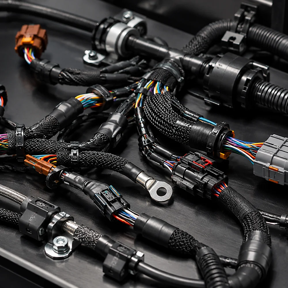
Signal Connection Harness
Connects sensors, encoders and control components where stable communication and accurate pin mapping are required.
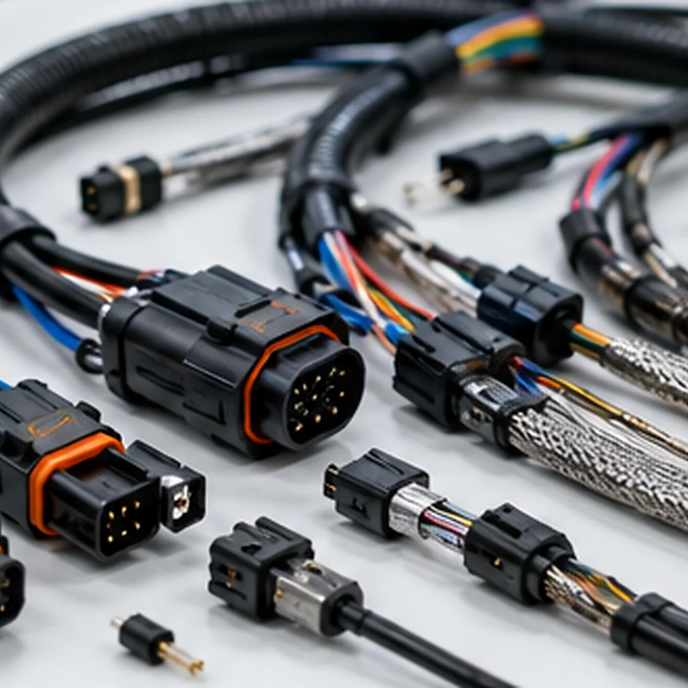
PTFE High-Temperature Harness
Uses PTFE or other suitable insulation for heat exposure and demanding robot environments.
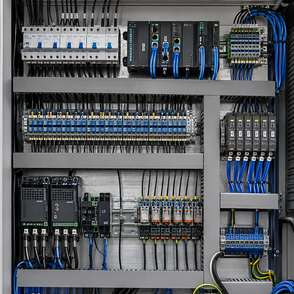
Power and Signal Combination Harness
Combines power and control circuits when electrical separation, shielding and routing are properly reviewed.

Robot Arm and Charging Interface Harness
Custom 8-pin, 9-pin, angled or charging-interface assemblies for robot arms and mobile systems.
Where Robotics Wiring Harnesses Are Used
Harness construction changes with equipment architecture, circuit function, movement, environment and installation method.

Industrial Robot Arms
Harnesses routed through articulated joints for motors, encoders, sensors and end effectors.
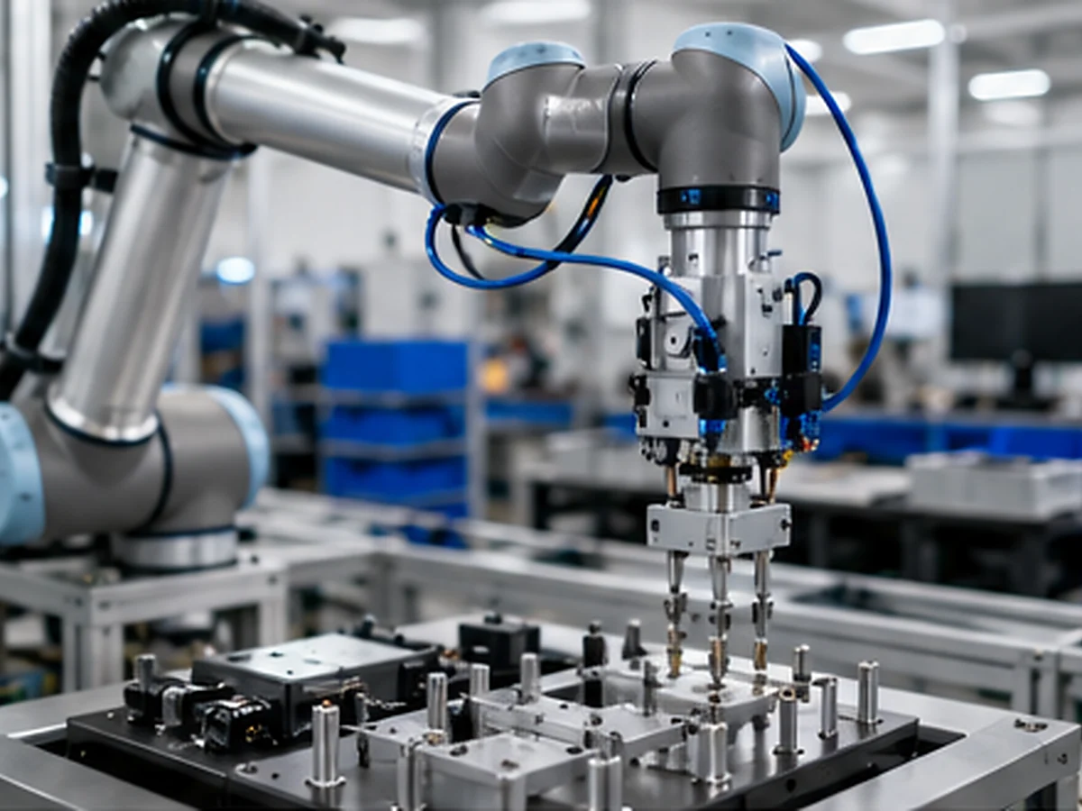
Collaborative and Assembly Robots
Compact power and signal assemblies for limited space and serviceable modular connections.
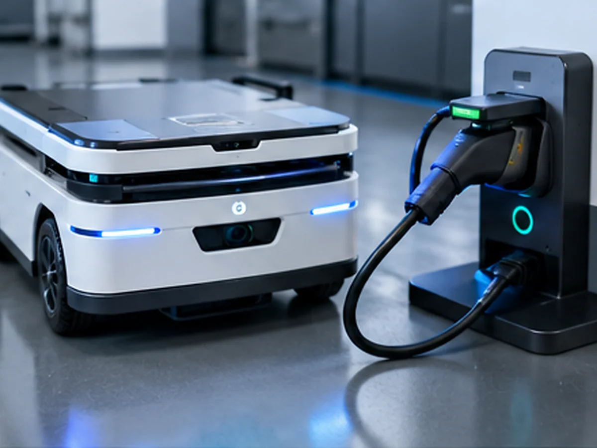
Mobile Robots and Charging Interfaces
Power, communication and charging harnesses for AGVs, AMRs and mobile robotic equipment.
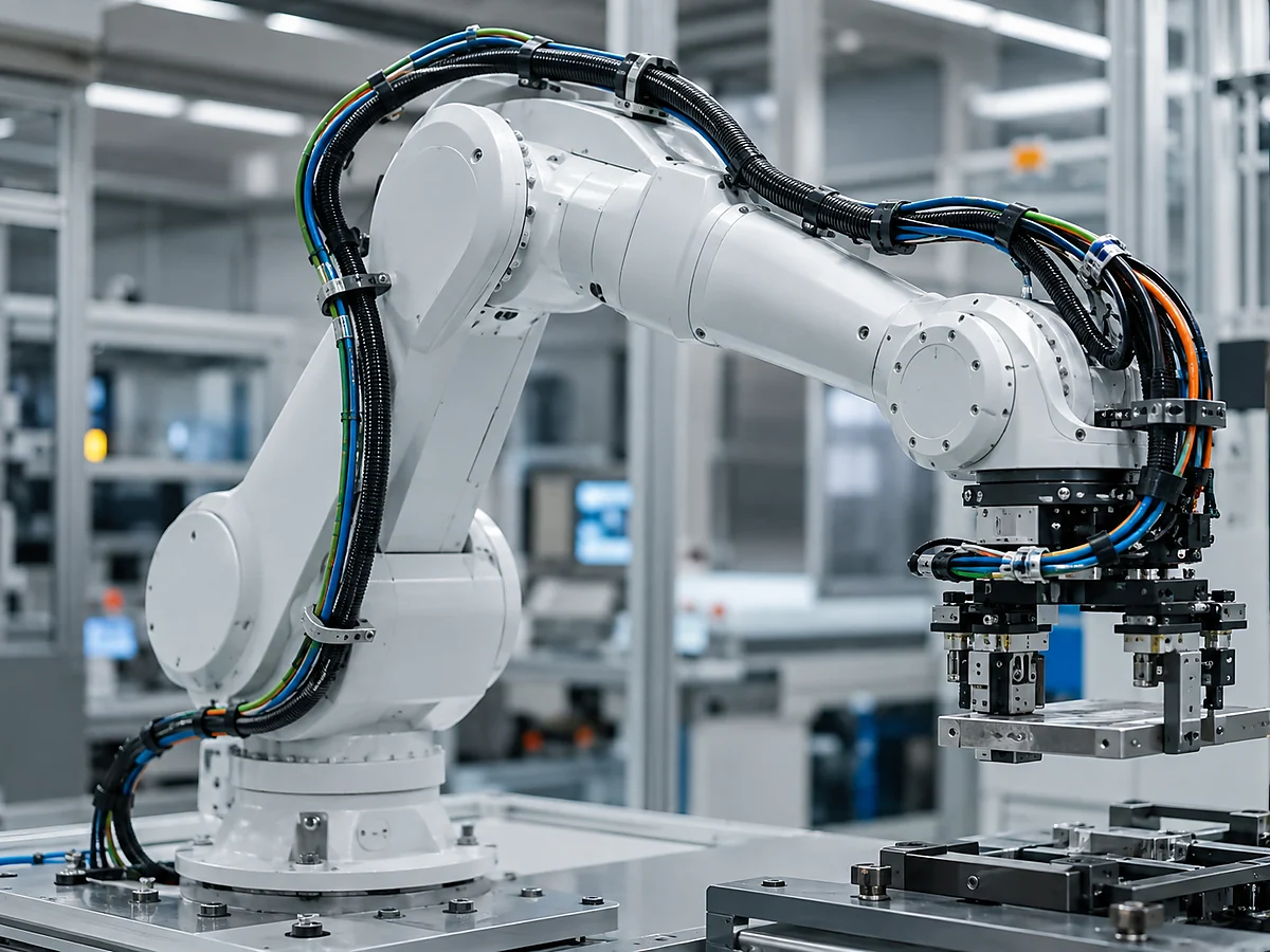
Automated Machines and End Effectors
Cable assemblies connecting grippers, vision systems, sensors, actuators and tool-change interfaces.
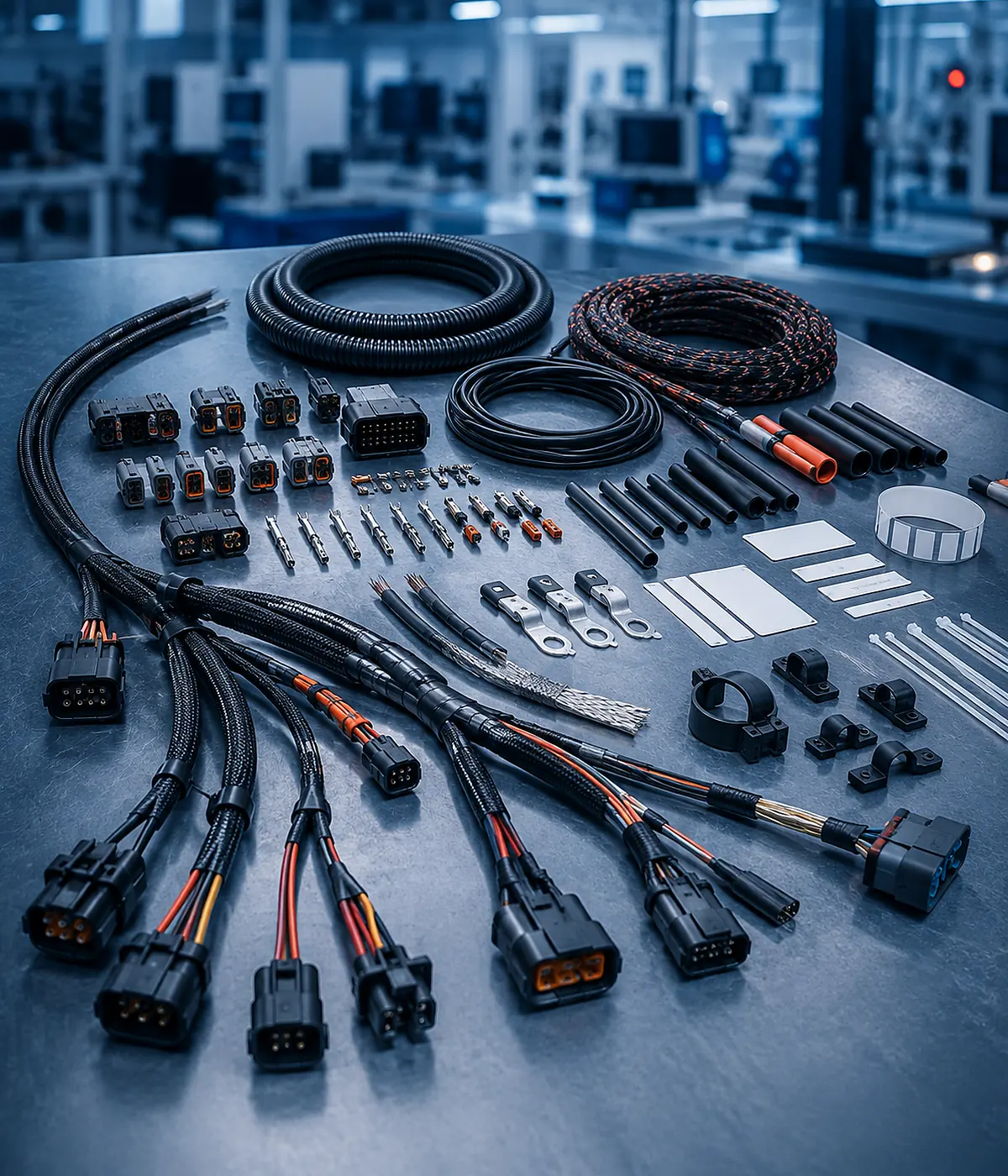
Engineering Options for the Approved Harness Design
Customization should be tied to a measurable requirement. Changing materials or connectors without understanding the electrical and mechanical consequences can create a cheaper BOM but a less reliable robotic system.
| Cable Construction | Fine-strand, high-flex, torsion-rated, PTFE, silicone or application-specific cable. |
| Connector Interface | Straight, angled, 8-pin, 9-pin, circular, rectangular and customer-specified connectors. |
| Circuit Arrangement | Motor power, brake, encoder, sensor, communication, charging and mixed circuits. |
| Mechanical Protection | Drag-chain jacket, braided sleeve, strain relief, abrasion protection and overmolding. |
| Routing | Axis-specific lengths, internal transitions, service loops and joint clearances. |
| Documentation | Pin map, axis labels, motion condition, drawing revision and test plan. |
Testing Should Match the Actual Failure Risk
Electrical continuity is important, but it does not prove every mechanical or environmental requirement. JowChain aligns inspection and validation items with the project specification.
| Electrical Continuity | Confirms pin mapping and detects open or incorrect circuits. |
| Shield and Ground Check | Verifies shield continuity and grounding for feedback or communication circuits. |
| Dimensional Inspection | Checks axis lengths, branch positions, connector orientation and service loops. |
| Connector Retention | Confirms terminal seating, locks and strain relief. |
| Static Bend and Fit Review | Checks routing against robot geometry before motion testing. |
| Cycle or Motion Validation | Project-specific movement testing can be planned when cycle life is critical. |
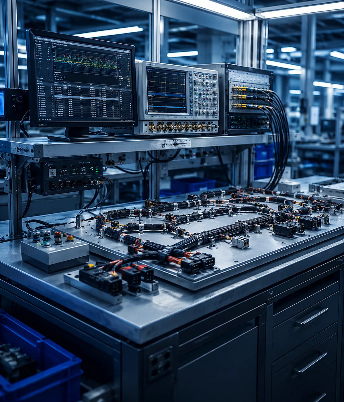
Robotic Arm Harness for Repeated Joint Movement and Sensor Feedback
An industrial arm required motor power, encoder feedback and sensor connections through several moving axes. A standard cable bundle would have created excessive bend stress and made maintenance difficult.
- Separated motor power from sensitive feedback circuits.
- Defined minimum bend radius and service loops by axis.
- Used compact angled connectors at restricted joints.
- Added axis labels and modular connection points.
- Planned fit verification before cycle validation.