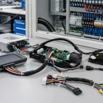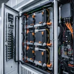
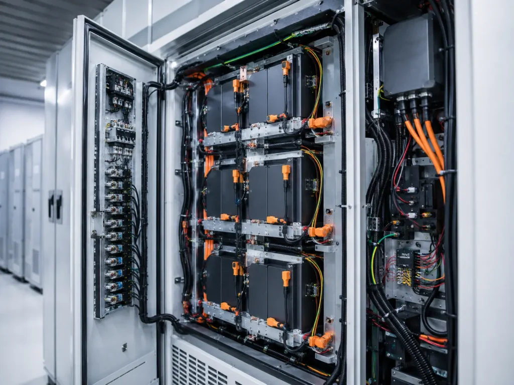
A commercial battery energy storage cabinet is installed for a solar-plus-storage project. The cells, BMS, PCS, battery modules and enclosure design all look correct during review. During commissioning, however, the system reports unstable voltage readings, unexpected temperature alarms, communication faults and intermittent module disconnection. Later inspection shows that several harnesses are routed too close to heat sources, one connector latch is not fully locked, some signal lines are too close to high-current cables, and a high-current terminal has higher resistance than expected.
This is why an Energy Storage Wiring Harness should never be treated as a secondary accessory. In battery systems, the harness affects BMS accuracy, thermal stability, insulation safety, service speed, module communication and long-term field reliability. A well-designed wiring harness helps the system read cell voltage correctly, detect temperature changes reliably, carry current safely, reduce maintenance confusion and support repeatable production quality.
For battery pack manufacturers, residential ESS brands, commercial and industrial storage integrators, solar storage companies, UPS manufacturers, PCS suppliers and energy storage cabinet builders, wiring design should start early. Buyers should define voltage level, current path, module layout, BMS connector details, temperature sensor type, communication method, insulation needs, routing conditions and test requirements before prototype production. A supplier that only quotes cable length and connector price may miss the real battery-system risks.
Why Energy Storage Wiring Harness Design Matters in Battery Systems
Battery energy storage systems rely on many electrical connections. Some carry high current. Some carry sensitive BMS sampling signals. Some connect temperature sensors. Some control fans, relays, contactors or auxiliary equipment. Some support CAN, RS485, Ethernet or dry contact signals. Each circuit has a different risk profile.
Power harnesses can create heat if wire gauge, terminal quality or contact resistance is wrong. BMS sampling harnesses can cause incorrect cell voltage readings if pinout, labeling or connector locking is weak. Temperature sensor harnesses can delay or distort thermal monitoring if the sensor location, connector or cable route is unstable. Communication harnesses can trigger system alarms if EMI shielding, grounding or route separation is poor.
Project buyers can contact an Energy Storage Wiring Harness supplier with system voltage, current rating, module layout, BMS pinout, sensor type, connector model, temperature range, flame-retardant requirements and annual volume. The more complete the technical input, the more accurately the supplier can recommend wire gauge, connector structure, insulation material, labeling, testing and traceability requirements.
| Selection Area | Battery System Risk | Buyer Should Confirm | Supplier Proof |
|---|---|---|---|
| Power circuit | Heating and voltage drop | Current rating, wire gauge, terminal resistance | Temperature-rise or current-rating data |
| BMS sampling | Wrong voltage reading | Pinout, wire ID, connector lock | 100% continuity and pinout test |
| Temperature sensing | Missed thermal issue | Sensor type, placement, response | Functional test record |
| Insulation | Short circuit and safety risk | Voltage rating, hi-pot, insulation resistance | Test report |
| Connector design | Loose connection | Locking, current rating, mating cycles | Connector datasheet |
| Routing | Abrasion and EMI | Bend radius, protection, separation | Harness drawing |
| Traceability | Field service difficulty | Batch ID, labels, revision control | Inspection and traceability record |
What Is an Energy Storage Wiring Harness?
Wiring Architecture Inside Battery Energy Storage Systems
An Energy Storage Wiring Harness is a custom cable assembly used to connect battery cells, battery modules, BMS boards, voltage sampling points, temperature sensors, current sensors, relays, contactors, fuses, PCS interfaces, communication modules, cooling fans, heaters and cabinet control systems.
Typical harness types include high-current power cables, module-to-module connections, BMS voltage sampling harnesses, temperature sensor harnesses, current sensor wiring, contactor and relay control wiring, fan and thermal management wiring, CAN or RS485 communication harnesses, auxiliary power wiring, grounding connections and cabinet control harnesses.
Where Energy Storage Wiring Harnesses Are Used
Energy storage wiring harnesses are used in residential battery energy storage systems, commercial and industrial ESS cabinets, solar-plus-storage systems, UPS battery systems, telecom backup power, microgrid battery systems, containerized battery storage, battery racks, lithium battery modules, portable energy storage units, EV charging energy storage equipment and grid-support battery systems.
A capable Energy Storage Wiring Harness manufacturer should understand both electrical and production requirements. The supplier should be able to support high-current cable processing, BMS signal harness assembly, sensor wiring, communication cable routing, insulation testing, labeling, traceability and project documentation.
Energy Storage Wiring Harness vs General Wire Harness
An energy storage harness is different from a general wiring harness because it supports battery safety, BMS accuracy, thermal monitoring and high-current reliability. A general harness may connect equipment controls or low-risk devices. A battery storage harness may influence protection logic, charging/discharging performance, system alarms and field safety.
| Factor | Energy Storage Wiring Harness | General Wire Harness |
|---|---|---|
| Main function | Battery power, BMS sampling, sensing and control | General electrical connection |
| Safety risk | Short circuit, heating, wrong sampling, insulation failure | Miswire or mechanical damage |
| Voltage/current | May involve high voltage and high current | Application-dependent |
| Signal sensitivity | BMS voltage, temperature and communication signals | General sensors and controls |
| Documentation | Strong traceability and test records needed | Varies by industry |
| Testing | Continuity, hi-pot, insulation, pull, functional checks | Basic electrical checks |
Step 1: Define the Battery System Architecture
Cell Module Rack and Cabinet Levels
Energy storage wiring changes by system level. At the cell group level, wiring may include voltage sense leads, temperature sensors, balancing connections and short internal routes. At the module level, the harness may connect BMS boards, module output cables, sensor lines and service connectors. At the rack level, wiring may support module interconnection, communication lines, cooling fan wiring and grounding. At the cabinet or container level, harnesses may connect PCS interfaces, DC bus links, auxiliary power, thermal management and safety signal circuits.
A residential wall-mounted ESS has different space, service and current requirements from a containerized grid storage system. A removable battery rack needs clear labels and service-friendly connectors. A compact battery module needs tight routing, secure locking and abrasion protection. A high-current cabinet needs thermal and insulation planning.
| System Level | Harness Focus | Main Risk |
|---|---|---|
| Cell group | Voltage sampling and temperature sensing | Wrong sampling or sensor error |
| Battery module | BMS connection and compact routing | Pinout mistake and tight space |
| Battery rack | Module interconnection and serviceability | Loose connector or poor labeling |
| Battery cabinet | High-current and control wiring | Heat, insulation and maintenance risk |
| Container ESS | Long routes and system integration | EMI, labeling and field service risk |
Step 2: Design High-Current Power Harnesses
Wire Gauge and Current Carrying Capacity
Power cables must be selected by continuous current, peak current, voltage, cable length, ambient temperature, bundle condition, insulation type, terminal type, derating and safety margin. A cable that is too small can create voltage drop and heat. A terminal with poor crimping or high contact resistance can become a thermal risk even when the cable gauge looks sufficient.
For battery systems, high-current harness design should be reviewed together with cabinet ventilation, terminal torque, fuse location, contactor position, cable bend radius and service access. A technically correct cable size can still fail if the lug is loose, the route is too tight, or the cable is exposed to heat without protection.
| Power Harness Factor | Why It Matters | Buyer Check |
|---|---|---|
| Wire gauge | Controls heating and voltage drop | Confirm continuous and peak current |
| Cable length | Affects resistance | Minimize unnecessary length |
| Terminal resistance | Affects heat generation | Check crimp or lug quality |
| Insulation rating | Supports voltage safety | Match system voltage |
| Temperature rise | Prevents overheating | Test under load where needed |
| Bend radius | Prevents cable damage | Confirm cabinet routing |
Terminal Lugs Torque and Contact Resistance
High-current connections fail when contact resistance increases. Common causes include loose lugs, improper crimping, wrong torque, oxidation, thermal cycling, vibration, poor plating, undersized terminals or incorrect washer stack. A small resistance increase can create meaningful heat under high current.
Recommended controls include torque specification, pull-force validation, crimp cross-section review, contact resistance checks, temperature-rise testing where needed and visual inspection. For field-serviceable battery cabinets, installation manuals should define torque and inspection steps clearly.
Step 3: BMS Voltage Sampling Harness Design
Why BMS Sampling Accuracy Matters
BMS voltage sampling affects state-of-charge calculation, cell balancing, overvoltage protection, undervoltage protection, fault detection and system alarms. If the BMS reads the wrong cell voltage, the battery system may make wrong protection decisions. This makes BMS harness accuracy a safety and reliability concern, not only a signal wiring detail.
Common BMS harness risks include wrong pinout, loose sampling wire, poor connector lock, label errors, harness damage, EMI interference, incorrect wire routing and unclear service identification. A sampling harness should be built from controlled drawings, tested with dedicated fixtures and labeled clearly for production and maintenance.
Pinout Control and Wire Identification
BMS harnesses require strict pinout control. Buyers should request drawing revision, pin table, wire color or marking, connector orientation, keyed connectors, terminal insertion check, 100% continuity testing, labeling, first article inspection and traceability records. The production team should not rely only on operator memory or manual visual matching.
| BMS Harness Item | Why It Matters | Supplier Control |
|---|---|---|
| Pinout | Prevents wrong cell reading | Electrical test fixture |
| Wire label | Supports assembly and service | Printed labels or color coding |
| Connector lock | Prevents loose contacts | Mating verification |
| Terminal insertion | Prevents intermittent signals | Pull and retention check |
| Insulation | Prevents short circuit | Hi-pot or insulation test |
| Routing | Prevents abrasion | Harness drawing and sleeve |
Step 4: Temperature Sensor and Thermal Management Wiring
Temperature Sensor Harnesses
Temperature sensing is important for battery safety and performance. Common sensing components include NTC thermistors, PTC sensors, RTD sensors, thermal switches and pack-level temperature probes. The harness must support stable sensor placement, reliable response, secure connector mating and clear service identification.
Sensor wiring should avoid heat sources that distort readings and mechanical routes that damage insulation. The sensor must stay in the intended position during vibration, maintenance and thermal cycling. A loose temperature sensor may report delayed or inaccurate temperature changes, reducing the value of the monitoring system.
Fan Heater and Thermal Control Harnesses
Energy storage cabinets may use cooling fans, airflow sensors, liquid cooling pumps, heaters, thermal switches, cabinet temperature sensors and humidity sensors. These harnesses must consider current, heat, vibration, condensation, service access and control logic. A fan harness failure may not immediately stop the system, but it can reduce cooling and increase thermal risk over time.
Step 5: Communication and Control Harness Design
CAN RS485 Ethernet and BMS Communication
Battery energy storage systems may use CAN, RS485, Ethernet, dry contact signals, relay control, contactor control, current sensor signals, PCS interfaces, EMS connections and auxiliary power. These circuits need stable pinout, route separation, connector locking and functional testing.
Communication harnesses should be designed around the requirements of the BMS, PCS and energy management system. Twisted pairs, shielding, grounding and impedance considerations may be needed depending on the communication type and cable length. Poor communication harness design can cause random alarms that are difficult to diagnose in the field.
EMI and Signal Separation
High-current DC cables, contactors, inverters and PCS equipment can create electrical noise. Sensitive signal lines should not be routed in long parallel paths beside high-current cables unless shielding and grounding are properly designed. Good practice includes separating power and signal routes, using twisted pairs where needed, controlling shield termination and following BMS or PCS supplier wiring guidance.
Step 6: Insulation Creepage Clearance and Safety Design
Voltage Rating and Insulation Selection
Energy storage systems may involve higher DC voltage than ordinary electronics. Buyers should confirm system voltage, insulation material, rated voltage, temperature rating, flame rating, abrasion resistance, chemical resistance, insulation thickness, sleeving, heat shrink and protective conduit.
Insulation should match the electrical and environmental risk. Cabinet edges, module frames, fan brackets and service openings can damage harness insulation if the routing is not protected. Flame-retardant and heat-resistant materials may be required depending on project requirements and installation location.
Creepage and Clearance Considerations
Harness routing should avoid unsafe distances between high-voltage conductors, low-voltage signal lines, enclosure metal parts and service areas. Connector spacing, terminal covers, insulating boots, barrier plates, cable clamps, protective sleeves, routing separation and warning labels should be reviewed during design.
It is important not to overclaim that a harness alone certifies an energy storage system. The harness supports system-level safety and compliance, but the battery system, BMS, PCS, enclosure, thermal design and installation must be evaluated together.

Step 7: Connector Selection for Battery Systems
Power Connectors and High-Current Terminals
Power connectors must be selected by current rating, voltage rating, temperature rating, contact resistance, locking design, touch protection, mating cycles, polarization, terminal plating, cable size and field service needs. A connector that is convenient for assembly may not be suitable for sustained high-current operation.
Bolted ring lugs, high-current DC connectors and module power connectors must be matched to installation torque, heat, vibration and service conditions. The connection interface should be protected from loosening and accidental touch where required.
Signal Connectors for BMS and Sensors
Signal connectors must consider pin count, pitch, locking, keying, terminal retention, mating orientation, wire gauge compatibility, service access, vibration resistance and mis-insertion prevention. BMS connectors should be difficult to insert incorrectly, and service labels should help technicians identify the correct harness quickly.
| Connector Type | Best Use | Buyer Risk |
|---|---|---|
| Ring lug | High-current bolted connection | Torque and contact resistance |
| High-current DC connector | Module or rack power connection | Heat and mating quality |
| Multi-pin signal connector | BMS sampling | Pinout and terminal insertion |
| Locking PCB connector | BMS board connection | Mating orientation |
| Waterproof connector | Outdoor cabinet interfaces | Seal and serviceability |
| Communication connector | CAN, RS485 or Ethernet | EMI and pin stability |
Step 8: Mechanical Protection and Routing Inside Battery Cabinets
Abrasion and Vibration Protection
Harnesses inside battery cabinets may rub against metal edges, module frames, brackets, fans, doors and service panels. Protection options include corrugated tube, braided sleeve, PVC sleeve, fiberglass sleeve, heat shrink, edge guards, grommets, cable clamps, tie mounts and protective conduits.
Routing should avoid sharp edges, moving parts, hot surfaces and excessive bend. Cable clamps should secure the harness without crushing insulation. Harnesses should not block airflow, service access or module replacement.
Serviceability and Replacement
Energy storage projects need maintenance over years of operation. Clear labels, modular connectors, accessible routing, spare harness availability, standardized lengths, connector keying, replacement instructions, maintenance manuals and cabinet drawings all support field service.
A professional Energy Storage Wiring Harness factory should be able to control material incoming inspection, crimping, lug processing, label printing, electrical testing, insulation testing, packing and traceability records. For battery systems, batch consistency is as important as the first sample.
Step 9: Testing and Quality Control
Electrical Tests
Electrical tests may include continuity, open/short testing, miswire testing, polarity testing, hi-pot, insulation resistance, contact resistance, voltage drop, shield continuity, functional BMS signal testing and sensor response testing. The test plan should match the circuit risk.
For BMS sampling harnesses, 100% continuity and pinout testing are critical. For high-current harnesses, contact resistance and temperature-rise review may be necessary. For sensor harnesses, functional response testing can help confirm that the sensor and wiring work as intended.
Mechanical and Process Tests
Mechanical and process tests may include crimp height, crimp cross-section, pull force, terminal retention, connector mating test, torque check, temperature-rise test, vibration test, bend test, visual inspection, label check, length tolerance and packing inspection. These checks reduce field failures and help suppliers maintain repeatable quality.
| Test | Purpose | ESS Value |
|---|---|---|
| Continuity | Confirms circuit path | Prevents open circuits |
| Miswire test | Checks pinout | Prevents BMS sampling errors |
| Hi-pot | Checks insulation withstand | Supports safety validation |
| Insulation resistance | Confirms insulation quality | Reduces leakage risk |
| Contact resistance | Checks connection quality | Prevents heating |
| Temperature rise | Validates current path | Prevents thermal risk |
| Pull force | Confirms crimp strength | Reduces field failures |
| Functional sensor test | Confirms sensing behavior | Supports thermal monitoring |
Step 10: Compliance and Documentation
Energy Storage Standards and Harness Documentation
Energy storage projects may reference UL 9540 for energy storage systems, UL 1973 for battery systems, UL 9540A for thermal runaway fire propagation evaluation, IEC 62619 for industrial lithium battery safety, NFPA 855 for stationary energy storage installations, IEC 60204-1 where machinery/equipment control applies, and RoHS/REACH for material compliance where required.
The harness itself does not replace system-level certification. However, good harness design and documentation support system-level review by improving insulation control, material traceability, wiring accuracy, thermal risk management, testing evidence and field maintenance clarity.
Supplier Documentation Package
A complete documentation package may include harness drawing, BOM, pinout table, wire gauge table, connector datasheets, cable datasheets, material declaration, RoHS/REACH documents, UL wire style information where required, inspection report, continuity test record, hi-pot test record, insulation resistance record, pull force record, first article inspection report, traceability record, labeling standard, packing photos, revision history and engineering change record.
Step 11: Supplier Selection and RFQ Checklist
What a Reliable Energy Storage Wiring Harness Supplier Should Provide
A reliable supplier should provide high-current cable assembly capability, BMS signal harness experience, crimping and lug processing, torque-control understanding, high-voltage insulation awareness, shielded communication cable experience, sensor harness assembly, continuity testing, hi-pot testing, insulation resistance testing, pull-force testing, contact-resistance testing, label control, traceability, prototype support, mass production, engineering review, packing control and failure analysis support.
Battery system buyers should not choose a supplier only by cable price. The correct supplier should ask technical questions before quoting: voltage, current, BMS pinout, module layout, connector model, route length, operating temperature, flame requirement, IP/sealing requirement, test plan and annual volume. A supplier who understands these details can reduce risk before production begins.
Buyer RFQ Checklist
| RFQ Item | Why It Matters | Buyer Requirement |
|---|---|---|
| Battery system type | Controls harness architecture | Residential, C&I, UPS, telecom, container or microgrid ESS |
| Voltage and current | Controls wire and insulation | System voltage, continuous current and peak current |
| BMS connector details | Controls sampling accuracy | Part number, pinout, pitch, lock and orientation |
| Power connector type | Controls thermal performance | Lug, DC connector, contactor terminal or custom connector |
| Sensor type | Controls monitoring function | NTC, PTC, RTD, thermal switch or custom probe |
| Routing path | Controls abrasion and EMI | Cabinet drawing, bend radius, protection and separation |
| Testing requirement | Controls quality confidence | Continuity, hi-pot, insulation, contact resistance or functional test |
Common Buyer Mistakes
Mistake 1: Treating BMS Wires as Simple Low-Voltage Wires
BMS wires may look small, but their accuracy matters. Wrong sampling, poor labels, loose connectors or pinout errors can create BMS alarms and unsafe protection decisions. Pinout control, connector locking and 100% electrical testing are essential.
Mistake 2: Ignoring Contact Resistance in High-Current Cables
High-current heating can come from poor lug crimping, loose bolts, bad plating, wrong torque or oxidized contact surfaces. Buyers should validate crimp quality, terminal selection, torque and contact resistance instead of checking only cable size.
Mistake 3: Poor Separation of Power and Signal Lines
Power cables, contactors and PCS equipment can create electrical noise. Poor route separation may cause communication faults, unstable sensing or repeated alarms. Signal lines should be routed and shielded based on system requirements.
Mistake 4: Weak Labeling and Traceability
Battery cabinets may require field maintenance years after installation. Weak labels, unclear revision records and no batch traceability can make replacement slow and risky. Clear labeling and controlled documents reduce service mistakes.
Mistake 5: Buying Only by Cable Price
Low unit price can create hidden costs through field failures, BMS alarms, certification delays, overheating, rework and project claims. Buyers should compare total reliability cost, not only cable assembly price.
Industry Trends in Energy Storage Wiring Harness Design
Higher System Voltage Requires Better Insulation Awareness
As ESS power levels rise, harness voltage rating, creepage, clearance, insulation material and connector design become more important. Battery storage buyers increasingly ask for more detailed insulation and test documentation.
BMS Accuracy Drives Better Signal Harness Control
Battery safety and performance depend on stable voltage sampling and temperature monitoring. This increases demand for controlled pinout, connector locking, wire labeling and 100% electrical testing.
Modular Battery Cabinets Need Service-Friendly Harnesses
Swappable modules and rack systems require clear labels, standardized connectors and accessible routing. A service-friendly harness can reduce field maintenance time and replacement errors.
C&I and Containerized ESS Increase Documentation Needs
Commercial and containerized energy storage projects often require inspection records, test reports, packing photos, traceability and compliance support. Documentation quality is becoming part of supplier competitiveness.
Thermal Risk Management Becomes More Important
Temperature sensor placement, fan harnesses, heater wiring and thermal monitoring circuits are increasingly important in battery cabinets. Harness design should support thermal detection and cooling reliability.
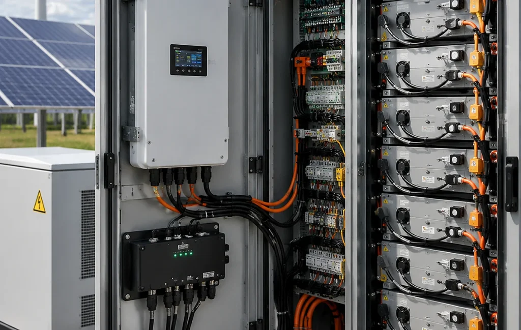
Final Recommendation: Design the Battery Harness Around Safety and Signal Accuracy
An Energy Storage Wiring Harness should be designed around battery architecture, current path, BMS signal reliability, insulation safety and long-term service. High-current cables require wire gauge, terminal quality, torque control and thermal review. BMS harnesses require pinout accuracy, labeling, connector locking and 100% testing. Sensor and communication harnesses require route separation, EMI awareness and functional verification.
Before requesting an Energy Storage Wiring Harness quote, prepare your battery system type, voltage, current, module/rack layout, BMS connector details, power connector type, pinout, cable length, sensor type, communication method, routing path, insulation requirements, test requirements and annual volume. A professional Energy Storage Wiring Harness supplier can help design a safer, more reliable and production-ready harness for battery energy storage systems.
Frequently Asked Questions About Energy Storage Wiring Harnesses
1. What is an Energy Storage Wiring Harness?
An Energy Storage Wiring Harness is a custom cable assembly that connects battery modules, BMS boards, voltage sampling lines, temperature sensors, power circuits, communication cables, relays, contactors, fans and cabinet control systems inside battery energy storage equipment. It supports power transmission, monitoring, sensing, communication and service functions. A well-designed harness improves battery safety, BMS accuracy, thermal monitoring, assembly speed and long-term reliability.
2. What is the difference between power harnesses and BMS signal harnesses?
Power harnesses carry current between battery modules, racks, contactors, fuses, PCS interfaces or DC bus connections, so they require correct wire gauge, insulation rating, terminal quality, contact resistance and temperature-rise control. BMS signal harnesses carry voltage sampling, temperature sensing and communication signals, so they require accurate pinout, clear labeling, connector locking, routing protection, EMI awareness and 100% electrical testing.
3. Why is BMS wiring accuracy important?
BMS wiring accuracy is important because the battery management system depends on correct cell voltage, temperature and communication signals to calculate state of charge, control balancing, detect faults and protect the battery from unsafe operation. A wrong pinout, loose sampling wire, mislabeled connector or intermittent signal can create false alarms, incorrect protection actions or missed fault detection. This is why BMS harnesses need strict drawings, labels, connector control and complete testing.
4. What tests should an Energy Storage Wiring Harness pass?
Common tests include continuity, open/short circuit testing, miswire testing, polarity testing, hi-pot testing, insulation resistance, contact resistance, voltage drop, pull force, terminal retention, temperature-rise testing and functional sensor or BMS signal testing. The exact test plan depends on whether the harness carries high current, BMS sampling signals, temperature sensor signals, communication circuits or cabinet control wiring. Critical battery harnesses should have traceable test records.
5. How do I choose an Energy Storage Wiring Harness supplier?
Choose an Energy Storage Wiring Harness supplier with high-current cable capability, BMS signal harness experience, crimp and lug process control, insulation testing, continuity testing, hi-pot testing, labeling control, traceability, documentation support, prototype support and mass production capacity. A reliable supplier should ask about voltage, current, module layout, BMS pinout, connector part numbers, sensor type, routing path, insulation requirements, compliance needs and annual volume before recommending a design.
References
- UL 9540 Standard for Energy Storage Systems and Equipment, Author: UL Standards Technical Committee, Institution: UL Standards & Engagement, Source: Energy Storage System Safety Standard.
- UL 1973 Batteries for Use in Stationary and Motive Auxiliary Power Applications, Author: UL Standards Technical Committee, Institution: UL Standards & Engagement, Source: Battery System Safety Standard.
- UL 9540A Test Method for Evaluating Thermal Runaway Fire Propagation in Battery Energy Storage Systems, Author: UL Standards Technical Committee, Institution: UL Standards & Engagement, Source: ESS Fire Propagation Test Method.
- NFPA 855 Standard for the Installation of Stationary Energy Storage Systems, Author: NFPA Technical Committee, Institution: National Fire Protection Association, Source: Stationary ESS Installation Standard.
- IEC 62619 Secondary Cells and Batteries Containing Alkaline or Other Non-Acid Electrolytes – Safety Requirements for Industrial Applications, Author: IEC Technical Committee Contributors, Institution: International Electrotechnical Commission, Source: Industrial Lithium Battery Safety Standard.
- IEC 60204-1 Safety of Machinery – Electrical Equipment of Machines, Author: IEC Technical Committee Contributors, Institution: International Electrotechnical Commission, Source: Machinery Electrical Equipment Standard.
- Battery Energy Storage System Design and Safety Guidance, Author: Energy Storage Technical Contributors, Institution: Energy Storage and Power Electronics Industry Publications, Source: Battery System Engineering Reference.
- Quality Management Systems Requirements, Author: ISO Technical Committee Contributors, Institution: International Organization for Standardization, Source: Quality Management Reference.
How Buyers Should Design and Source Energy Storage Wiring Harnesses
How should buyers start an Energy Storage Wiring Harness project?
Buyers should start with battery architecture, voltage level, current path, BMS connector layout, module/rack structure, sensor locations, communication method, routing space and test requirements. Harness design should be part of the battery system engineering process, not a late-stage accessory.
Why is BMS wiring accuracy so important?
BMS wiring accuracy affects cell voltage readings, balancing, SOC calculation, protection logic and alarm reliability. A wrong pinout, loose terminal or mislabeled sampling wire can create serious system faults.
What option works best for high-current energy storage cables?
High-current cables should be selected by wire gauge, terminal resistance, insulation rating, contact resistance, temperature rise, bend radius, lug quality and torque control. Cable size alone is not enough if the connection interface is weak.
What option works best for BMS signal harnesses?
BMS signal harnesses need strict pinout control, wire identification, keyed connectors, locking structures, clear labels, route protection and 100% continuity testing. For sensitive communication circuits, shielding and route separation may also be required.
Consideration: What creates the highest battery harness risk?
The highest risks come from wrong BMS sampling, high contact resistance, poor insulation, loose connectors, weak labeling, poor power/signal separation, insufficient testing and missing traceability records.
Recommendation
Select the harness as a safety-critical battery subsystem. Confirm electrical design, mechanical routing, materials, labels, tests, documentation and supplier process control before moving from prototype to mass production.
Send your supplier the battery system type, module layout, voltage/current, BMS pinout, connector part numbers, sensor type, routing drawings, insulation requirements and test plan. A qualified Energy Storage Wiring Harness supplier can recommend a safer and more production-ready cable assembly.