

Electronic Wire Harnesses for Compact Reliable Equipment Integration
JowChain manufactures electronic wire harnesses for control boards, sensors, actuators, displays, power supplies and device assemblies. Projects can be customized around PCB connectors, fine-gauge wires, shielding, compact routing, labels and installation requirements.
Electronic Harness Design Must Balance Space, Signal Integrity and Assembly Efficiency
JowChain electronic wire harnesses organize power, signal and communication circuits inside industrial and commercial electronic equipment. Typical projects include PCB-to-wire harnesses, sensor and actuator connections, control-panel wiring, display and interface cables, shielded signal assemblies and mixed power/signal harnesses. Final electrical ratings depend on the selected conductor, terminal, connector and installation environment.
Electronic equipment often places multiple circuit types inside a limited enclosure. Power supply lines, sensor signals, communication cables and control connections may run close together, making pin mapping, shielding, routing and connector selection critical to reliable operation.
JowChain separates the project into circuit function, mechanical installation and production requirements. This helps determine wire gauge, connector pitch, shielding, labels, branch structure and test method before the harness reaches the equipment assembly line.
Compact Routing
Branch geometry and connector orientation are designed around enclosure space and assembly access.
Signal Management
Shielding, twisted pairs and grounding requirements can be specified for sensitive circuits.
PCB Connector Compatibility
Harnesses can be built around project-specified board connectors, terminals and locking systems.
Installation Efficiency
Clear labels, keyed connectors and organized branches reduce assembly mistakes and service time.

Electronic Equipment Connectivity Product and Circuit Options
These solution directions are starting points. Final harness construction should follow the approved electrical architecture, installation drawing, connector list and validation plan.
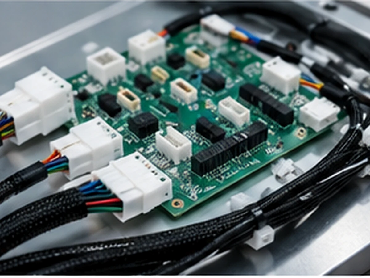
PCB-to-Wire Harness
Connects circuit boards to power supplies, sensors, switches, displays and external interfaces.
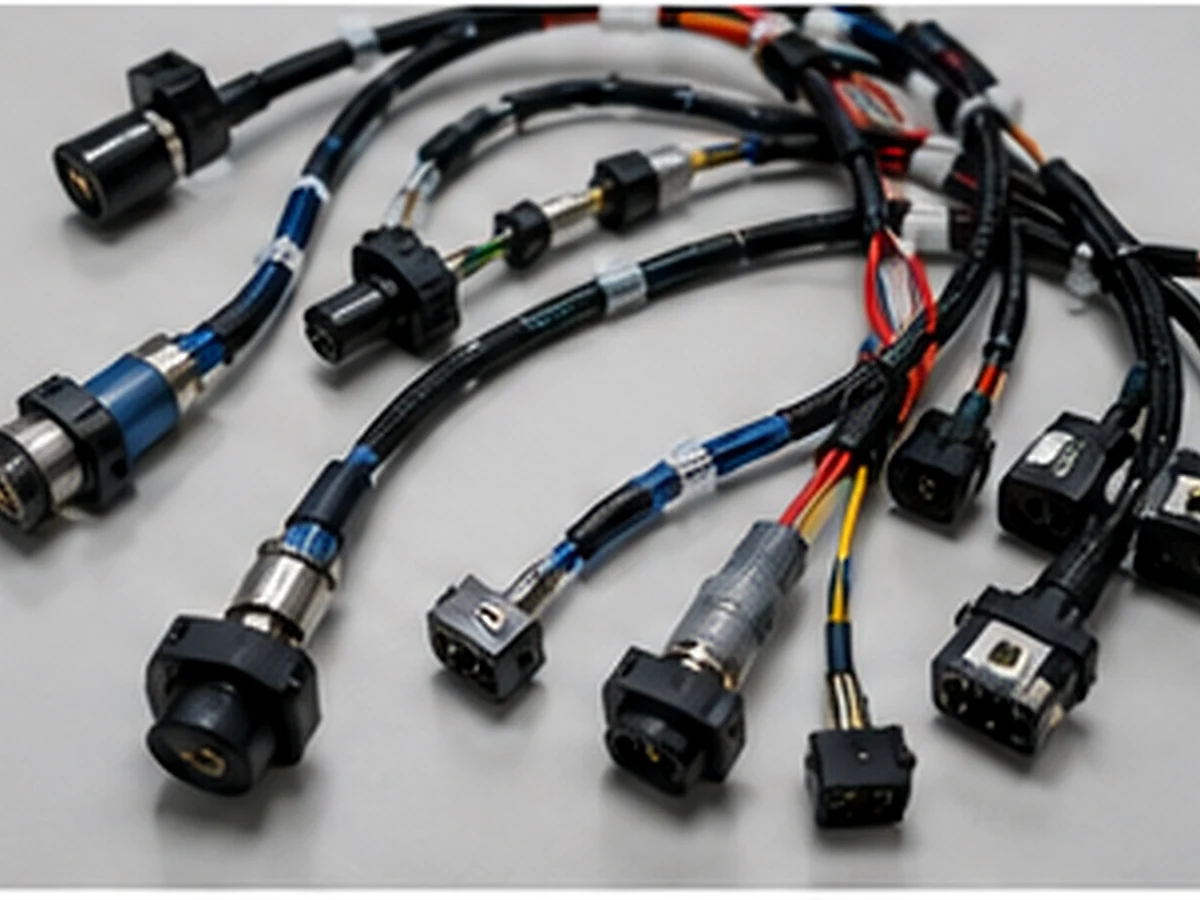
Sensor and Actuator Harness
Carries control signals and low-power connections to sensors, solenoids, relays and actuators.
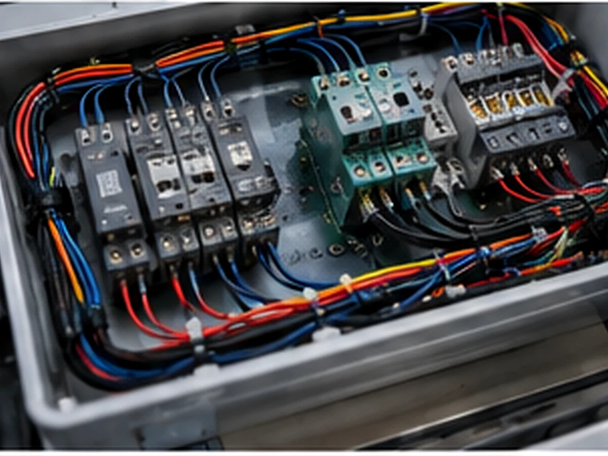
Control Panel Wiring Harness
Organizes internal cabinet or panel wiring with labels, branch separation and connectorized installation.
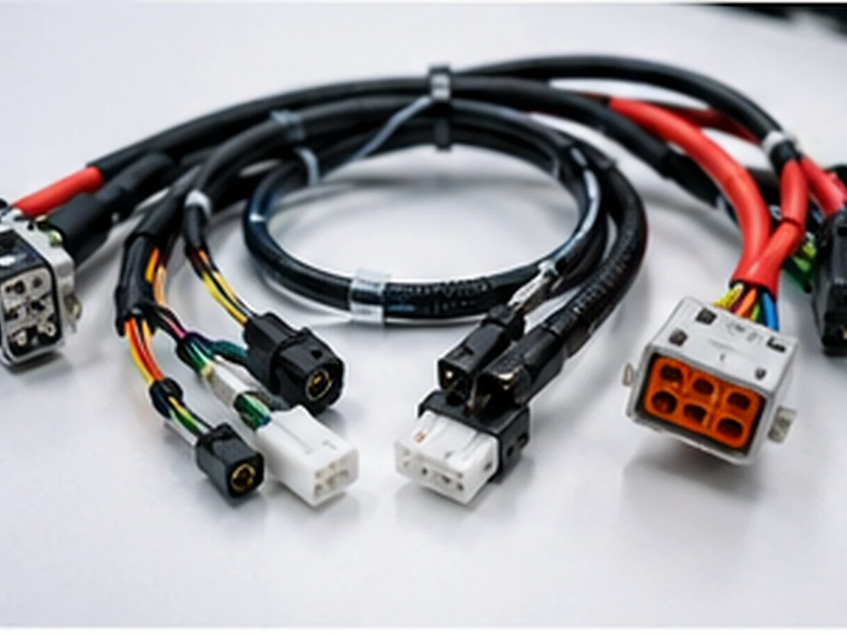
Mixed Power and Signal Assembly
Combines power, control and communication circuits where the design and shielding strategy are clearly defined.
Where Electronic Wire Harnesses Are Used
Harness design changes with equipment architecture, circuit function, environment and installation process. Each application should be reviewed independently.
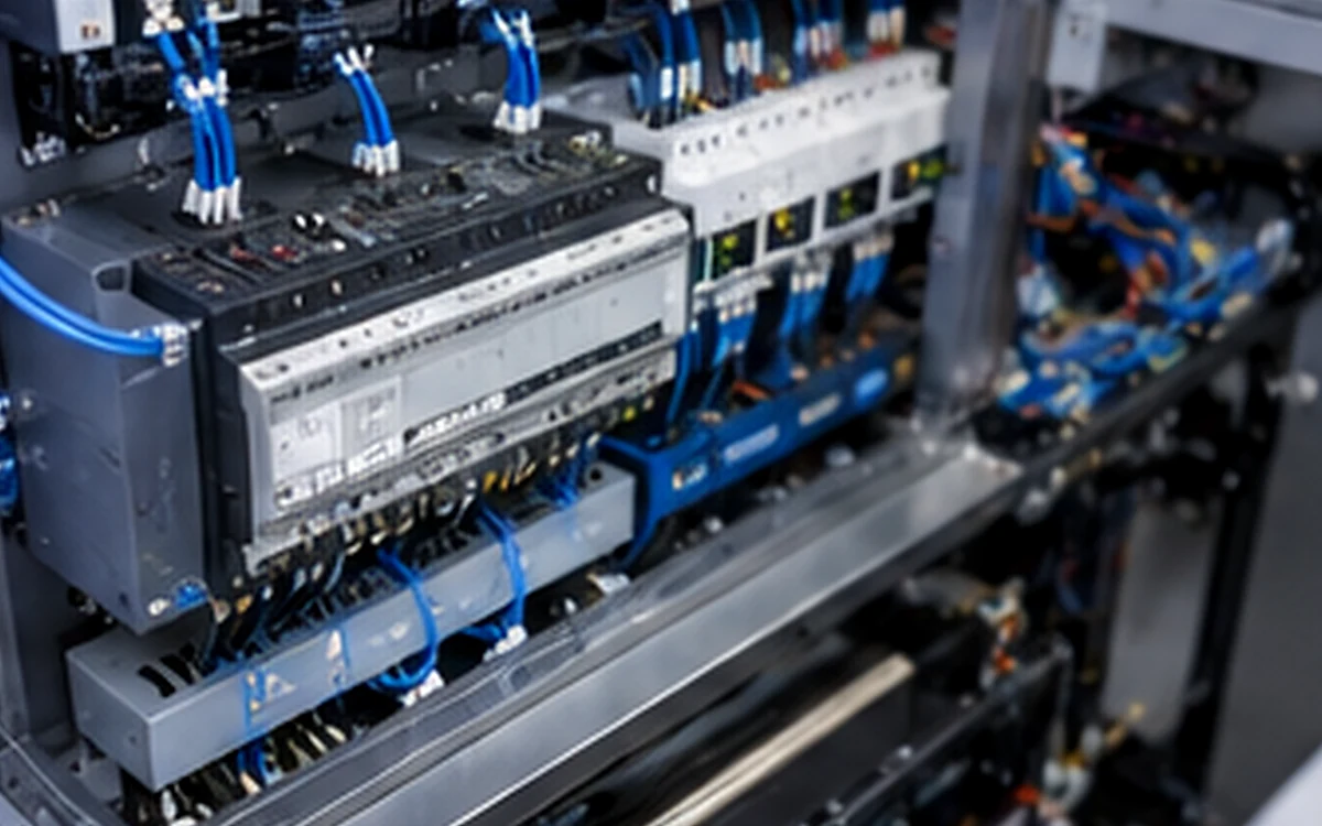
Industrial Control Equipment
Harnesses for PLCs, relays, sensors, HMIs, control cabinets and machine-control assemblies.
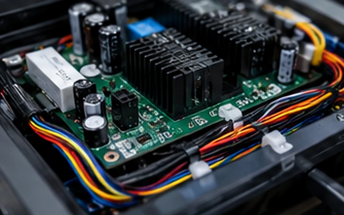
Commercial Electronic Devices
Internal wiring for displays, power supplies, interfaces and modular electronic products.
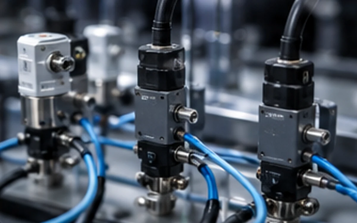
Instrumentation and Sensors
Low-level signal connections requiring accurate pin mapping, clear identification and stable routing.
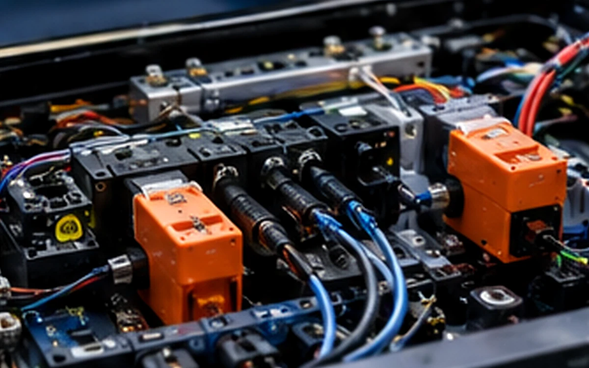
Power and Communication Modules
Mixed assemblies connecting power conversion, control boards and communication interfaces.
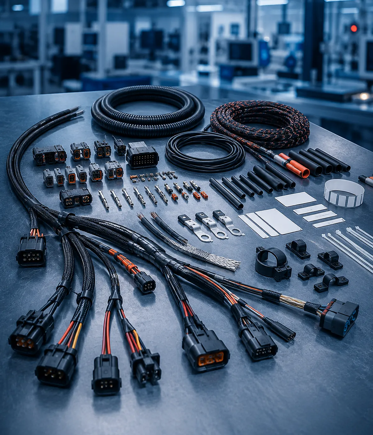
Engineering Options for the Approved Harness Design
Customization should be tied to a measurable requirement. Changing materials or connectors without understanding the electrical and mechanical consequence can create a cheaper BOM but a less reliable system.
| Wire and Cable | Gauge, color, insulation, twisted pairs, shielding and jacket construction. |
| PCB and Device Connectors | Specified housings, terminals, headers, plugs, circular connectors and locking systems. |
| Routing | Branch geometry, breakout positions, minimum bend radius and enclosure-specific dimensions. |
| Identification | Wire numbers, labels, heat-shrink markers, connector IDs and assembly instructions. |
| Protection | Sleeves, heat-shrink, strain relief, overmolding and abrasion protection. |
| Documentation | Pin map, drawing revision, BOM, first-article record and test instructions. |
Testing Should Match the Actual Failure Risk
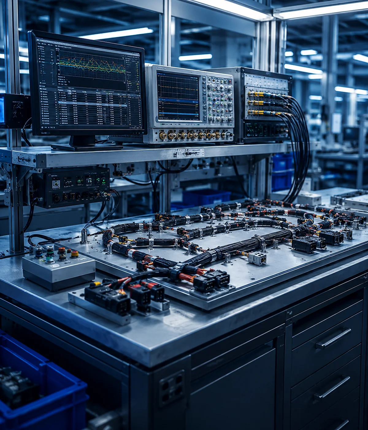
Electrical continuity is important, but it does not prove every mechanical or environmental requirement. JowChain can align inspection and validation items with the project specification.
| Pin-to-Pin Continuity | Confirms the intended circuit and detects wiring or terminal-position mistakes. |
| Short-Circuit Check | Verifies that isolated circuits are not unintentionally connected. |
| Dimensional Inspection | Checks cable length, branch position and connector orientation against the approved drawing. |
| Connector Retention | Confirms terminals and locks are seated correctly where required. |
| Shield and Ground Review | Checks shield termination and grounding arrangement for sensitive signal assemblies. |
| Functional Support | Project-specific test fixtures or customer functional validation can be planned when needed. |

Electronic Control Unit with Multiple Sensors and Limited Enclosure Space
An industrial electronic module required board connections, external sensors and a power supply harness inside a compact enclosure. The challenge was to prevent connector confusion while maintaining bend radius and service access.
- Separated power and low-level signal branches.
- Used keyed connectors and clear labels.
- Defined connector orientation for assembly access.
- Confirmed pin mapping with electrical continuity testing.
- Locked harness dimensions after enclosure fit verification.