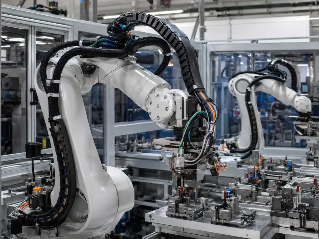
An automation line uses six-axis robots for pick-and-place, welding, packaging, palletizing or precision assembly. During the first month, the robot performs smoothly. After thousands or millions of cycles, alarms begin. An encoder signal becomes unstable. A gripper cable breaks near the wrist joint. A camera cable loses connection. A drag chain jacket cracks. Maintenance replaces the cable assembly, but the same failure returns because the original harness was designed like a static industrial cable, not a motion-critical robot component.
A Robotics Wiring Harness is not simply a connectorized cable bundle. It is a dynamic electrical assembly that must keep power, signal, sensor, servo, encoder, vision and end-effector circuits stable while the robot bends, twists, accelerates, stops, rotates and repeats the same motion every day. In continuous-flexing applications, the harness must be designed around motion profile, not only voltage and wire length.
For industrial robot OEMs, cobot integrators, automation equipment builders, end-effector manufacturers and procurement teams, the hidden cost of a weak harness is much higher than the cable price. A failed robot harness can stop a production cell, trigger alarms, damage connectors, reduce robot uptime and create emergency maintenance work. Buyers planning a new robotic system can contact a Robotics Wiring Harness supplier with robot type, axis count, bend radius, torsion angle, signal type, connector requirements and cycle-life targets to receive a more accurate design recommendation.
Why Robotics Wiring Harness Design Fails Under Continuous Flexing
Most harness failures in robotic systems do not happen because the wire cannot conduct electricity during a bench test. They happen because the harness is repeatedly bent, twisted, pulled, compressed, vibrated or rubbed during actual robot motion. A static continuity test confirms the circuit path at one moment, but it does not prove that the harness can survive millions of motion cycles.
A professional Robotics Wiring Harness manufacturer should review the robot’s real motion profile before recommending wire, jacket, shielding, connector, overmold, strain relief or routing design. The supplier should understand that drag chain bending, robot joint torsion, servo power delivery, encoder signal stability and camera data transmission create different design risks. The right harness is selected by the movement environment, not by connector count alone.
| Selection Area | Continuous-Flex Risk | Buyer Should Confirm | Supplier Proof |
|---|---|---|---|
| Motion profile | Cable fatigue | Bend radius, torsion angle, cycle count | Motion review or test plan |
| Cable construction | Conductor breakage | Fine-strand conductor and high-flex design | Cable datasheet |
| Jacket material | Abrasion or cracking | PUR, TPU, TPE or application-specific jacket | Material specification |
| Shielding | Signal noise | Braid/foil coverage and grounding method | Cable structure and test record |
| Connector exit | Stress concentration | Strain relief, overmold and clamp design | Sample and pull test |
| Drag chain routing | Cable wear | Separation, fill rate and bend radius | Routing drawing |
| Testing | Hidden fatigue defects | Continuity, hi-pot, flex and torsion tests | Test records |
What Is a Robotics Wiring Harness?
Motion-Critical Wiring for Robot Systems
A Robotics Wiring Harness connects power, control, signal, sensor, encoder, communication, vision, pneumatic/electrical end-effector and safety-related circuits inside or around a robot system. It may be routed through robot arms, along external brackets, inside drag chains, around rotating joints, across tool changers or into moving end-effectors.
Common applications include six-axis industrial robots, SCARA robots, delta robots, collaborative robots, Cartesian robots, welding robots, painting robots, packaging robots, palletizing robots, semiconductor handling robots, medical device automation robots, AGV/AMR docking systems, vision-guided cells and robotic grippers.
Robotics Wiring Harness vs Standard Industrial Wire Harness
A standard industrial harness may be mostly static. It may sit in a cabinet, connect fixed sensors or route along a machine frame. A robot harness often moves continuously. It may bend in a drag chain, twist inside a robot wrist, carry servo power to a moving axis or transmit encoder and camera signals during acceleration.
| Factor | Robotics Wiring Harness | Standard Industrial Harness |
|---|---|---|
| Motion | Continuous bending and torsion | Mostly static or limited movement |
| Failure mode | Fatigue, signal loss, jacket cracking | Loose terminals, oil, heat, vibration |
| Cable choice | High-flex and torsion-resistant cable | General industrial cable |
| Routing | Robot joints, drag chains, moving arms | Cabinets and machine frames |
| Signal risk | Servo, encoder, camera and sensor noise | Motor and sensor noise |
| Design focus | Motion lifecycle and compact routing | Electrical load and environment |
Understanding Continuous Flexing in Robot Applications
Bending Torsion and Multi-Axis Movement
Continuous flexing is not one simple movement. Bending means the cable repeatedly curves in one direction, which is common in drag chains. Torsion means the cable twists around its own axis, which is common in robot arms and wrist joints. Multi-axis movement combines bending, twisting, pulling, compression, vibration and acceleration at the same time.
This distinction is critical. A cable suitable for a drag chain may not be suitable for torsion. A cable suitable for static sensors may fail quickly on a robot joint. A high-flex cable used in a linear axis may still fail if it is clamped incorrectly or forced through a tight bend near a connector.
Robot Motion Profile and Cycle Life
Buyers should define the robot’s motion profile before selecting the harness. Important data includes cycles per hour, cycles per day, expected service life, maximum and minimum bend radius, torsion angle, robot speed, acceleration, cable length, fixing points, moving distance, temperature, oil exposure, coolant exposure and maintenance interval.
| Motion Factor | Why It Matters | Buyer Question |
|---|---|---|
| Bend radius | Controls conductor fatigue | What is the minimum bend radius? |
| Torsion angle | Controls twisting stress | How many degrees does the joint rotate? |
| Cycle count | Controls lifetime target | How many cycles per year? |
| Acceleration | Controls dynamic force | Is the robot high-speed? |
| Fixing points | Controls stress concentration | Where is the cable clamped? |
| Cable weight | Affects robot movement | Does the cable restrict motion? |
Cable Construction for High-Flex Robotics Harnesses
Fine-Strand Conductors and Flex Life
High-flex robot cables often use fine-strand copper conductors to reduce fatigue compared with larger rigid strands. The conductor design, strand count, lay length, bunching method and core structure all influence flex life. If the conductor is too stiff, repeated bending can eventually break strands and create intermittent faults before a complete open circuit appears.
For servo power cables, current capacity and heat must be balanced with flexibility. For signal cables, conductor stability and shielding performance must be protected during movement. For vision and Ethernet cables, impedance stability and data integrity become especially important.
Insulation and Jacket Materials
Material choice affects flex life, abrasion resistance, oil resistance, low-temperature performance, heat resistance and cable diameter. Common options include PVC, PUR, TPU, TPE, XLPE, silicone and fluoropolymer materials for special conditions. No material is best for every robot. The correct choice depends on motion, environment, signal type and cost target.
| Material | Strength | Robotics Use | Buyer Risk |
|---|---|---|---|
| PVC | Cost-effective | Limited-motion applications | May crack in high-flex zones |
| PUR/TPU | Abrasion and oil resistance | Drag chains and robot cells | Higher cost |
| TPE | Flexibility and low-temperature performance | Moving arms and cobots | Chemical resistance must be checked |
| XLPE | Heat and electrical performance | Power/control circuits | Flex design must be verified |
| Silicone | Heat and flexibility | Special heated zones | Needs abrasion protection |
| FEP/PTFE | Chemical and heat resistance | Harsh special environments | Higher cost and processing complexity |
Drag Chain Wiring Harness Design
Bend Radius and Cable Separation
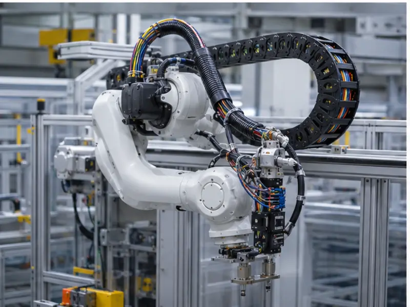
Drag chains are common in Cartesian robots, gantry systems, packaging automation, machine tending cells and linear axes. The harness inside a drag chain must follow a controlled bend radius, move smoothly and avoid twisting. Cable separation is important because cables can rub, tangle or generate heat if the chain is overfilled.
Good drag chain routing uses correct bend radius, cable separation, proper fill ratio, no twisted installation, no over-tight cable ties, smooth motion path, proper cable length and abrasion-resistant jacket material. If a drag chain is too small, too crowded or poorly arranged, even a good cable may fail early.
Common Drag Chain Failures
Drag chain failures often appear as conductor breakage, jacket cracking, cable twisting, shield damage, connector stress, signal interruption, cable abrasion, heat buildup or chain jamming. Many failures are caused by routing rather than cable quality alone.
| Drag Chain Issue | Likely Cause | Prevention |
|---|---|---|
| Broken conductor | Bend radius too small | Use correct high-flex cable |
| Jacket wear | Cable rubbing | Use separators and proper fill |
| Cable twisting | Wrong installation | Install without twist |
| Signal loss | Shield fatigue | Use flex-rated shielded cable |
| Connector damage | No strain relief | Add clamp, boot or overmold |
| Chain jamming | Overfilled chain | Control fill ratio |
Robot Arm and Joint Routing
Torsion-Resistant Harness Design
Robot arms often twist and rotate through multiple axes. This creates torsion, not only bending. A torsion-resistant robot harness should consider rotational angle, cable loop allowance, joint clearance, anti-pinch routing, lightweight construction, strain relief, connector exit angle, mounting brackets, sleeving and protection.
If the harness is routed too tightly around a joint, it can restrict motion or create stress concentration. If the harness is too loose, it may rub against the robot body or surrounding tooling. Successful routing gives the cable enough movement freedom without allowing uncontrolled abrasion.
Internal vs External Robot Harness Routing
Internal routing protects the harness and creates a clean robot appearance, but replacement can be harder. External routing is easier to inspect, replace and retrofit, but it is more exposed to damage. Drag chain routing controls linear movement, while tool-side routing supports end-effectors, grippers, sensors and quick-change tooling.
| Routing Type | Advantage | Risk | Best Use |
|---|---|---|---|
| Internal routing | Clean appearance and protection | Difficult replacement | OEM robot arms |
| External routing | Easier service and retrofit | Exposure to damage | End-effectors and automation cells |
| Drag chain routing | Controlled linear movement | Requires correct fill and radius | Cartesian robots and machine axes |
| Tool-side routing | Easy tool change | Connector stress | End-effectors |
| Hybrid routing | Balanced flexibility | More design complexity | Custom robot systems |
Servo Power Encoder Sensor and Vision Cable Requirements
Servo Motor Power Harnesses
Servo motor harnesses must carry power while surviving motion. Buyers should review current rating, voltage rating, shielding, grounding, thermal behavior, oil resistance, dynamic flexibility, connector locking and mechanical strain relief. Servo power lines can also become noise sources, so routing and shielding must be coordinated with encoder and signal cables.
Encoder and Feedback Cables
Encoder cables require signal integrity. A weak shield, poor connector, unstable impedance or tight bending near the connector can create intermittent feedback errors. The robot may alarm, lose position stability or stop unexpectedly. Encoder cable routing should be separated from power cables where possible, and shield termination should be defined clearly.
Sensor Camera and Ethernet Cables
Modern robot cells increasingly use cameras, force sensors, proximity sensors, vacuum sensors, gripper feedback, Ethernet/IP, PROFINET, industrial Ethernet, USB and vision cables. These circuits need bandwidth, shielding, bend resistance, connector locking, EMI control and stable route separation. A camera cable that passes a static data test may still fail when repeatedly bent or twisted.
EMI Shielding and Signal Integrity
Why EMI Is Critical in Robotic Systems
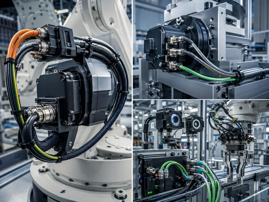
Robots often work near servo drives, electric motors, welding power supplies, inverters, industrial networks and high-speed switching devices. EMI can create encoder noise, camera dropout, false sensor triggers, communication alarms, robot stops, poor repeatability and safety circuit faults.
Signal integrity should be designed from the beginning. It is not enough to add shielding after failures occur. The harness layout should separate power and signal circuits, define grounding points, protect shield continuity and prevent mechanical damage to the shield during flexing.
Shielding Grounding and Cable Separation
Buyers should define braid or foil shielding, shield coverage, drain wire, grounding point, 360-degree shielding where required, connector shielding, power/signal separation, cable tray routing and EMI test requirements. For dynamic applications, the shield must also survive movement. A shield that cracks or fatigues during flexing can gradually reduce noise protection.
Connector Overmold and Strain Relief Design
Why Connector Exit Is a Common Failure Point
Many robot harness failures occur near connector exits or clamp points. This is where flexible cable meets a rigid connector, housing, overmold or bracket. If the cable bends sharply at this transition, the conductor, shield or jacket may fatigue early.
Common causes include sharp bend angles, no strain relief, rigid overmold, wrong cable clamp, repeated pulling, connector vibration, heavy cable weight and tool-side movement. Good design uses boots, bend relief, overmolding, clamps or flexible support to spread stress over a longer cable section.
Overmolded vs Assembled Connectors
Overmolded connectors can provide strong sealing and strain relief, making them useful for high-flex robot cables, washdown environments and compact end-effectors. Field-assembled connectors can be easier to replace, but they depend heavily on assembly quality. Circular connectors, M8/M12 connectors and custom connectors each have different benefits and limitations.
| Connector Type | Advantage | Limitation | Best Use |
|---|---|---|---|
| Overmolded connector | Strong sealing and strain relief | Less repairable | High-flex robot cables |
| Field-assembled connector | Easy replacement | Assembly quality risk | Maintenance and retrofit |
| Circular connector | Robust and common | Larger size | Servo and sensor systems |
| M8/M12 connector | Compact and standardized | Pin and current limits | Sensors and I/O |
| Custom connector | Optimized fit | Lead time and MOQ | OEM robot projects |
Testing and Validation for Continuous Flexing Harnesses
Electrical Tests
Electrical tests may include continuity, open circuit, short circuit, miswire, hi-pot, insulation resistance, contact resistance, voltage drop, shield continuity, signal testing and functional testing. These tests confirm that the harness is assembled correctly and that circuits meet basic electrical requirements.
However, static electrical tests are not enough for robot applications. A harness can pass continuity today and fail after repeated flexing. This is why dynamic validation should be considered for critical robot motion zones.
Mechanical and Dynamic Tests
Mechanical and dynamic tests may include flex cycling, torsion cycling, pull force, connector retention, bend radius validation, cable abrasion, vibration, temperature cycling, oil resistance, drag chain trials and robot motion trials. The test plan should match the motion environment. A drag chain harness needs flex validation; a robot wrist harness needs torsion validation; a servo or encoder harness may need signal performance validation during movement.
| Test | Purpose | Robotics Value |
|---|---|---|
| Continuity | Confirms circuit path | Basic quality control |
| Hi-pot | Checks insulation withstand | Power and safety circuits |
| Shield continuity | Confirms EMI protection | Encoder and vision cables |
| Flex cycle test | Simulates repeated bending | Predicts cable fatigue |
| Torsion test | Simulates robot joint twisting | Validates robot arm use |
| Pull force | Confirms crimp and connector strength | Prevents terminal failure |
| Vibration test | Checks mechanical stability | Robot motion reliability |
| Functional signal test | Confirms application performance | Prevents intermittent alarms |
Standards Compliance and Documentation
Harness Workmanship and Acceptance
For cable and harness workmanship, buyers may use IPC/WHMA-A-620 as an acceptance reference where appropriate. It can support inspection expectations for wire preparation, crimp quality, soldered joints where used, strain relief, mechanical securing, sleeving and related assembly criteria.
For robotics projects, workmanship must be combined with motion validation. A harness can look acceptable at the bench but still fail if it is routed through the wrong bend radius or exposed to torsion beyond its design limit.
Robot Safety and Machine Integration
Robot safety is broader than the harness itself. Industrial robot systems require risk assessment, guarding, emergency stop logic, safe maintenance access, proper cable routing and integration review. Harness routing should not create pinch points, restrict movement, interfere with protective equipment or make maintenance unsafe.
Safety-related circuits should be clearly documented and tested according to the system design. If the harness connects emergency stop, safety interlock, enabling device or protective circuit functions, the buyer and system integrator should define the required validation process before production.
Supplier Documents Buyers May Request
Useful documents may include cable datasheets, connector datasheets, material declarations, RoHS, REACH, UL cable information where required, inspection reports, test records, FAI reports, traceability records, drawing revision records, dynamic flex test reports and installation guidance. Documentation helps buyers compare suppliers more accurately and supports long-term maintenance planning.
Supplier Selection and RFQ Checklist
What a Robotics Wiring Harness Supplier Should Provide
A capable supplier should support high-flex cable sourcing, torsion-resistant cable sourcing, servo/encoder/sensor cable experience, crimping, soldering where needed, overmolding, harness boards, continuity testing, hi-pot testing, shield continuity testing, pull force testing, dynamic validation support, traceability, small-batch prototypes, mass production and engineering review.
Before approving a supplier, buyers should review the production process, testing capability and factory control system. A professional Robotics Wiring Harness factory should be able to show how incoming materials, crimping, connector assembly, shielding, overmolding, inspection and final testing are controlled for repeatable production. For motion-critical robot applications, the supplier’s process discipline is as important as cable selection.
Buyer RFQ Checklist
| RFQ Item | Why It Matters | Buyer Requirement |
|---|---|---|
| Robot type | Controls motion profile | Six-axis, SCARA, delta, cobot, Cartesian or custom robot |
| Axis count | Controls bending and torsion zones | Provide movement range and axis function |
| Cable function | Controls cable structure | Servo power, encoder, sensor, camera, I/O or end-effector |
| Motion data | Controls flex-life requirement | Bend radius, torsion angle and cycle target |
| Connector details | Controls fit and reliability | Part numbers, pinout, sealing, locking and exit direction |
| Environment | Controls material choice | Temperature, oil, coolant, abrasion, dust and IP requirement |
| Testing | Controls validation confidence | Continuity, hi-pot, shield, flex, torsion or functional test |
Common Buyer Mistakes
Mistake 1: Using Static Cable in Moving Robot Arms
Static cable may pass initial testing but fail early in robot motion. Robot arms need cable selected for bending, torsion and repeated movement. High-flex or torsion-rated cable should be used where the application requires it.
Mistake 2: Ignoring Bend Radius
If the bend radius is too small, conductor fatigue and jacket cracking can occur. The cable, routing path, drag chain size and fixing points must all match the required minimum bend radius.
Mistake 3: No Strain Relief at Connectors
Connector exits are common failure points. Without strain relief, the cable may bend sharply at the connector, creating early conductor or shield failure. Boots, clamps, overmolds and flexible support can reduce stress concentration.
Mistake 4: Mixing Power and Signal Cables Poorly
Poor separation between servo power and signal cables can create encoder noise, camera dropout, false sensor signals and robot alarms. Shielding, grounding and routing separation should be defined in the design stage.
Mistake 5: No Dynamic Testing
A harness that passes bench testing may still fail during robot movement. Critical applications should consider flex testing, torsion testing or real robot motion validation before mass production.
Industry Trends in Robotics Wiring Harness Design
More Collaborative Robots Require Compact Flexible Harnesses
Collaborative robots need lightweight routing, compact connectors and flexible cables because their arms are smaller, more accessible and often used in flexible production cells. Harnesses must support motion without restricting robot speed or safety function.
Vision Systems Increase Signal Integrity Requirements
Machine vision, industrial Ethernet and camera-based inspection are becoming common in robot cells. This increases demand for high-flex signal cables, better shielding and stable connector designs.
Robot End-Effectors Are Becoming More Modular
Grippers, tool changers, sensors and vacuum systems increasingly use plug-and-play harness designs. This improves maintenance speed but requires strong connector durability and clear labeling.
Predictive Maintenance Increases Demand for Traceability
Factories want better lifecycle data and replacement planning. Traceability, test records and installation documentation help maintenance teams identify risk before unexpected downtime occurs.
High-Flex Cable Materials Continue to Improve
PUR, TPU, TPE and specialty jacket materials continue to support longer motion life, better abrasion resistance and improved performance in oil, coolant and low-temperature conditions.
Final Recommendation: Choose Robotics Wiring Harnesses by Motion Profile First
A Robotics Wiring Harness should be selected by motion profile, signal reliability and service-life target. Static wire size is not enough. Buyers should review bend radius, torsion angle, drag chain routing, cable construction, jacket material, shielding, connector strain relief, overmolding, EMI control and dynamic testing before approving production.
Before requesting a Robotics Wiring Harness quote, prepare your robot type, axis count, application, motion profile, bend radius, torsion angle, cycle target, voltage/current, signal type, connector part numbers, routing path, EMI environment, IP rating, test requirements and annual volume. A professional continuous flex wiring harness supplier can help design a high-flex, signal-stable and motion-ready harness for continuous robot operation.
Frequently Asked Questions About Robotics Wiring Harnesses
1. What is a Robotics Wiring Harness?
A Robotics Wiring Harness is a motion-ready cable assembly that connects power, control, signal, encoder, sensor, vision, communication and end-effector circuits in robot systems. Unlike a static harness, it must survive repeated bending, torsion, vibration, acceleration, abrasion and connector stress. It is commonly used in six-axis robots, SCARA robots, collaborative robots, Cartesian robots, welding robots, packaging robots, palletizing robots, machine vision systems and robotic grippers.
2. What makes a Robotics Wiring Harness different from a standard harness?
A Robotics Wiring Harness is different because it must work under continuous motion. Standard industrial harnesses are often mostly static, while robot harnesses may bend in drag chains, twist inside robot arms, move around joints and carry sensitive servo, encoder, camera or sensor signals. This requires high-flex or torsion-resistant cables, proper bend radius, shielding, strain relief, connector locking, dynamic testing and careful routing design.
3. What cable material is best for continuous flexing robot applications?
PUR, TPU and TPE are commonly used for continuous flexing robot applications because they can offer flexibility, abrasion resistance, oil resistance or low-temperature performance depending on the formulation. However, the best material depends on bend radius, torsion angle, cycle-life target, temperature, oil or coolant exposure, cable diameter, signal type and installation environment. Buyers should request cable datasheets and confirm whether the cable is suitable for drag chain, torsion or multi-axis robot movement.
4. Why do robot harnesses fail near connectors?
Robot harnesses often fail near connectors because the cable bends sharply at the connector exit or clamp point. Other causes include no strain relief, rigid overmold design, repeated pulling, connector vibration, heavy cable weight, wrong clamp position or tool-side movement. Strain relief boots, flexible overmolds, support clamps and proper routing can reduce stress concentration and improve service life in moving robot applications.
5. How do I choose a Robotics Wiring Harness supplier?
Choose a Robotics Wiring Harness supplier with high-flex cable knowledge, torsion cable experience, servo and encoder cable capability, shielding design support, overmolding options, crimp process control, continuity testing, hi-pot testing, shield continuity testing, pull force testing, dynamic flex or torsion validation support and traceability. A qualified supplier should ask about robot type, axis count, motion profile, bend radius, torsion angle, signal type, connector part numbers, IP rating, EMI environment and cycle-life target before recommending a design.
Reesferenc
- IPC/WHMA-A-620F Requirements and Acceptance for Cable and Wire Harness Assemblies, Author: IPC and WHMA Technical Committee, Institution: IPC International and WHMA, Source: Cable and Wire Harness Assembly Standard.
- ISO 10218-1:2025 Robotics – Safety Requirements – Industrial Robots, Author: ISO Technical Committee Contributors, Institution: International Organization for Standardization, Source: Industrial Robot Safety Standard.
- ISO 10218-2:2025 Robotics – Safety Requirements – Robot Systems, Robot Applications and Robot Cells, Author: ISO Technical Committee Contributors, Institution: International Organization for Standardization, Source: Robot System Safety Standard.
- ANSI/A3 R15.06-2025 Industrial Robots and Robot Systems – Safety Requirements, Author: Association for Advancing Automation Contributors, Institution: ANSI and A3, Source: U.S. Industrial Robot Safety Standard.
- ISO 13849 Safety of Machinery – Safety-Related Parts of Control Systems, Author: ISO Technical Committee Contributors, Institution: International Organization for Standardization, Source: Machinery Safety Control Reference.
- IEC 60204-1 Safety of Machinery – Electrical Equipment of Machines, Author: IEC Technical Committee Contributors, Institution: International Electrotechnical Commission, Source: Machinery Electrical Equipment Standard.
- Industrial Ethernet and Motion Control Cabling Guidance, Author: Automation Engineering Contributors, Institution: Industrial Automation Technical Publications, Source: Robot Signal and Cable Design Reference.
- Quality Management Systems Requirements, Author: ISO Technical Committee Contributors, Institution: International Organization for Standardization, Source: Quality Management Reference.
How Buyers Should Design a Robotics Wiring Harness for Continuous Flexing
How should buyers start a Robotics Wiring Harness project?
Buyers should start by defining robot type, axis count, movement range, bend radius, torsion angle, cycle target, cable function and routing path. The harness must be designed around motion before wire gauge and connector count are finalized.
Why does continuous flexing create higher failure risk?
Continuous flexing repeatedly stresses conductors, insulation, shields, jackets and connector exits. A cable that works in a static test may fail when it bends or twists millions of times in a robot cell.
What option works best for drag chain applications?
Drag chain applications need high-flex cables, correct bend radius, chain fill control, cable separation, abrasion-resistant jackets and twist-free installation. Overfilled or undersized chains can reduce harness life even when the cable quality is good.
What option works best for robot arm joints?
Robot arm joints need torsion-resistant cable, compact routing, controlled loop allowance, anti-pinch design, strain relief and connector exit protection. Internal routing should also consider replacement difficulty and maintenance access.
Consideration: What creates the highest robot harness failure risk?
The highest risks come from using static cable, ignoring bend radius, missing strain relief, poor power/signal separation, weak shielding, no dynamic testing and routing cables through joints without twist control.
Recommendation
Select the harness as a motion-critical assembly. Confirm cable structure, jacket material, shielding, connector design, routing, dynamic testing and supplier traceability before mass production. For robot applications, the lowest cable price is rarely the lowest lifetime cost.
Send your supplier the robot model, axis motion, routing photos, connector part numbers, signal type, bend radius, torsion angle, environment and cycle-life target. A qualified Robotics Wiring Harness supplier can recommend a safer design for continuous robot operation.