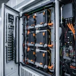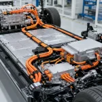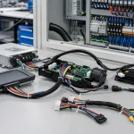
A smart home controller, industrial control module, LED display system, portable device, power supply unit or sensor gateway may pass prototype testing perfectly. The PCB works. The enclosure looks clean. The firmware is stable. The first sample looks ready for production. But after pilot assembly, problems appear: intermittent power, loose connectors, reversed polarity, sensor noise, display flicker, battery overheating, EMC test failure or difficult final assembly. The issue is not always the PCB. Very often, the weak point is the Electronic Wire Harness.
An electronic harness is small compared with the enclosure, PCB and display, but it directly affects product reliability, assembly speed, electrical safety, signal stability, compliance and after-sales cost. A poor harness can turn a well-designed electronic device into a field-return problem. A well-designed harness makes assembly easier, reduces wiring mistakes, improves serviceability and helps the device pass production testing more consistently.
Why Electronic Wire Harness Design Matters More Than It Looks
Electronic products are becoming smaller, smarter and more connected. Many devices now combine microcontrollers, wireless modules, displays, batteries, LED drivers, sensors, fans, motors, power supplies, communication ports and control boards in compact enclosures. These functions create more internal wiring requirements, but available space becomes smaller.
For this reason, an electronic harness should be designed from product function, PCB interface and signal stability rather than wire length alone. If a harness connects two PCBs, connector pitch, mating height, orientation and pinout accuracy matter. If it carries battery power, polarity control, current rating, insulation and heat management matter. If it carries sensor or display signals, shielding, grounding and routing separation matter. Buyers preparing a new project can contact an Electronic Wire Harness supplier with drawings, connector part numbers, voltage/current data, pinout tables, enclosure space and compliance requirements to avoid early design mistakes.
| Selection Area | Electronics Risk | Buyer Should Confirm | Supplier Proof |
|---|---|---|---|
| PCB connector | Loose or wrong mating | Pitch, lock, orientation, mating height | Connector datasheet |
| Wire gauge | Heat or voltage drop | Current rating and length | Wire specification |
| Pinout | Miswire or reverse polarity | Drawing, color code, keying | 100% continuity test |
| Shielding | EMI or signal noise | Braid, foil, twisted pair, grounding | Cable structure |
| Strain relief | Broken wires near connector | Clamp, boot, adhesive, overmold | Pull test |
| Insulation | Safety and durability | Voltage, flame, temperature rating | Material datasheet |
| Compliance | Market access delay | RoHS, REACH, UL style where required | Documents |
What Is an Electronic Wire Harness?
Compact Wiring for Electronic Devices and Control Systems
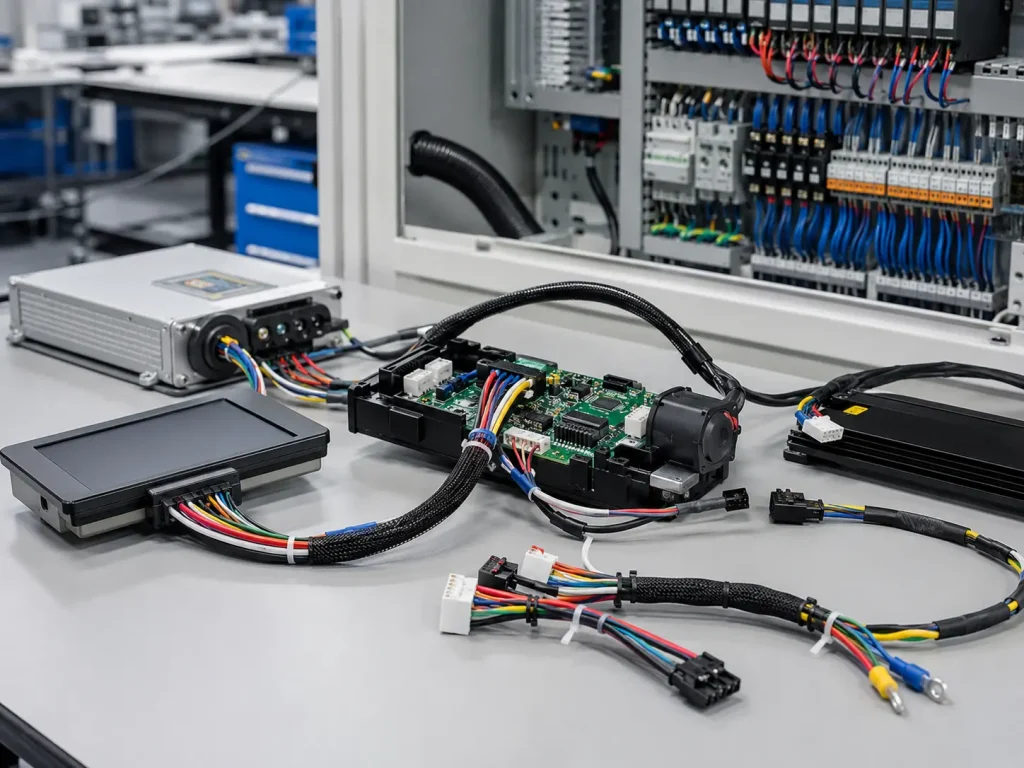
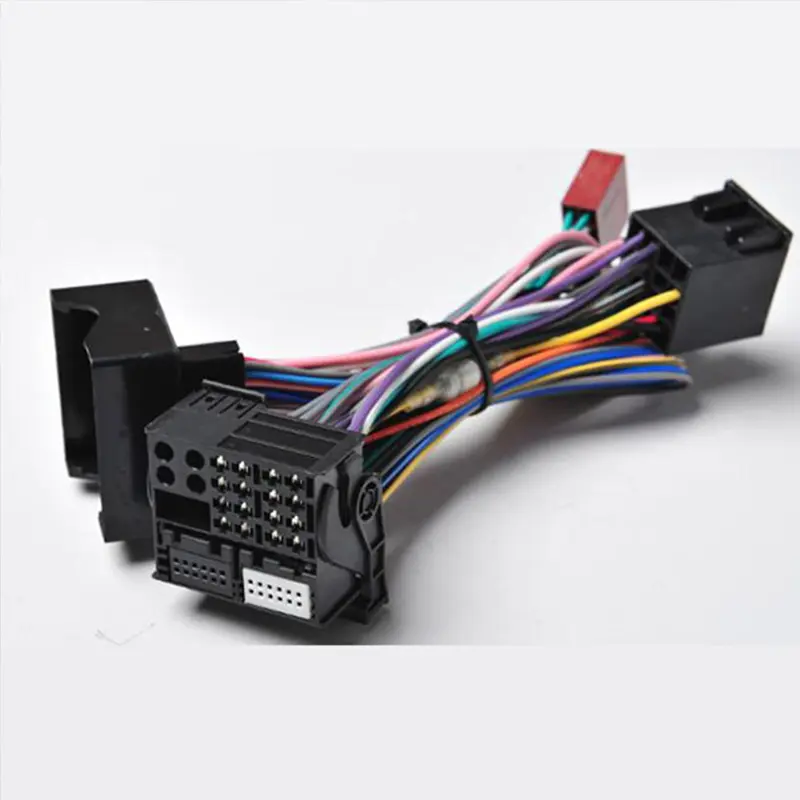
An Electronic Wire Harness is a pre-assembled set of wires, terminals, connectors, sleeves, labels, shielding, insulation and protective parts used to connect electronic modules inside or around a device. It may connect PCB to PCB, PCB to battery, PCB to display, PCB to sensor, PCB to fan, PCB to switch, PCB to LED module, PCB to power supply, PCB to motor or a control board to enclosure-mounted components.
In consumer electronics, harnesses are often compact, cost-sensitive and high-volume. In industrial electronics, they may need stronger locking, higher temperature resistance, EMI protection, field service labeling and traceability. A professional Electronic Wire Harness manufacturer should understand both types of products because a smart home device and an industrial controller may use similar connector families but very different reliability priorities.
Typical Applications
Consumer applications include smart home devices, speakers, displays, LED lighting, portable devices, home appliances, charging equipment, gaming devices, battery-powered products and small home-use equipment. Industrial applications include control panels, power supplies, sensor gateways, industrial displays, HMI modules, automation controllers, inverters, PLC-related modules, test equipment, communication devices, industrial IoT systems and machine control electronics.
Electronic Wire Harness vs Standard Wire Harness
An electronic harness usually works in a tighter space with smaller connectors and more PCB-related constraints. It must fit inside the enclosure, avoid interference with screw bosses and heat sinks, match connector orientation, protect signal quality and support efficient production assembly. A general wire harness may focus more on power distribution, equipment routing or mechanical environment.
| Factor | Electronic Wire Harness | General Wire Harness |
|---|---|---|
| Size | Compact, small pitch, tight enclosure | Larger and more flexible |
| Interface | PCB, sensor, display, battery, module | Machine, vehicle, equipment |
| Main risk | Miswire, EMI, connector looseness | Load, routing, environment |
| Connector type | Small-pitch PCB, FFC/FPC, IDC, battery connectors | Automotive or industrial connectors |
| Testing | Continuity, polarity, hi-pot, signal check | Continuity, pull, environmental checks |
| Design focus | PCB mating, compact routing, compliance | Power distribution and mechanical routing |
Step 1: Define the Electronic Product Function
Consumer Electronics Harness Needs
Consumer electronics harnesses usually prioritize compact size, clean appearance, low voltage, fast assembly, cost control, repeatability, RoHS-related material control and stable packaging. Typical risks include connector loosening during assembly, polarity mistakes, trapped wires, excessive harness length, display flicker, battery lead damage, no strain relief and poor label control.
For example, a smart speaker may use internal harnesses for battery, charging port, microphone board, LED indicator, speaker module and control PCB. If cable length is too short, final assembly becomes difficult. If it is too long, the wire may be pinched by the enclosure. If polarity is not controlled, the battery circuit may be damaged. The harness must support both electrical function and assembly process.
Industrial Electronics Harness Needs
Industrial electronic products usually prioritize vibration resistance, EMI shielding, temperature range, terminal retention, serviceability, connector locking, traceability, compliance documentation and long service life. A sensor gateway, HMI panel or power module may be installed in a machine cabinet or factory environment where heat, electrical noise and maintenance access are important.
Industrial buyers should consider whether connectors need locking latches, whether labels must be service-friendly, whether shield termination must be defined and whether the harness can be replaced in the field. A design that is acceptable for a consumer device may not be robust enough for an industrial controller.
Step 2: Select Wire Gauge Voltage and Current Rating
Current Carrying Capacity
Wire gauge should be selected by operating current, peak current, wire length, voltage drop, ambient temperature, bundle density, connector current rating, terminal current rating and safety margin. A wire that looks physically small and neat may still become a heat risk if the current is too high or the enclosure has poor ventilation.
Battery leads, motor leads and power supply leads deserve special attention because they may carry higher current. Signal wires may carry low current but require higher attention to routing, pinout and noise. Buyers should never assume that connector pin count alone defines electrical capacity.
| Circuit Type | Common Current Level | Buyer Focus |
|---|---|---|
| Signal wire | Low current | Noise control and pinout accuracy |
| LED wire | Low to medium current | Voltage drop and color coding |
| Fan wire | Low to medium current | Connector locking and vibration |
| Battery lead | Medium to high current | Insulation, polarity and heat |
| Motor lead | Medium to high current | Current rating and EMI |
| Power supply lead | Application-dependent | Safety margin and connector rating |
Voltage Drop and Heat Risk
Even low-voltage electronics can fail if the wire gauge is too small or the harness is too long. Voltage drop can cause display flicker, unstable sensors, weak motors, battery charging problems or controller resets. Heat risk can also increase when wires are bundled tightly inside a closed plastic or metal enclosure.
For compact devices, thermal behavior should be reviewed together with board layout and enclosure design. If the harness passes a short bench test but fails after long operation, current rating, connector resistance and enclosure temperature should be checked.
Step 3: Connector Selection for Electronic Wire Harnesses
PCB Connector Pitch and Locking Design
Connector selection is one of the most important decisions in electronic harness design. Buyers should confirm pitch, pin count, voltage rating, current rating, mating height, locking structure, friction lock, latch design, polarization, keying, mounting orientation, cable exit direction, mating cycles, terminal retention and crimp terminal compatibility.
Small-pitch PCB connectors are useful in compact devices, but they can also increase assembly risk. Operators may insert terminals incorrectly, damage pins, misalign connectors or struggle with weak locking feel. If a connector is too small for the assembly process, production yield may suffer.
Small-Pitch Connector Risks
Small connectors save space, but they reduce tolerance for error. Problems may include wrong terminal insertion, pin damage, connector misalignment, weak terminal retention, difficult manual assembly, no polarity protection, high rework rate and poor mating feel. For high-volume consumer electronics, these problems can become expensive quickly.
| Connector Area | Design Concern | Buyer Check |
|---|---|---|
| PCB connector | Mating accuracy | Pitch, lock and orientation |
| Battery connector | Safety and polarity | Keying and current rating |
| Sensor connector | Signal stability | Shielding and locking |
| Display connector | Space and bend | FFC/FPC or flexible cable option |
| Fan connector | Vibration | Locking and retention |
| External interface | User handling | Durability and strain relief |
Step 4: Signal Integrity and EMI Control
Why EMI Matters in Electronic Wire Harnesses
Electronic products may include microcontrollers, wireless modules, switching regulators, displays, sensors, motors, LED drivers, inverters and communication ports. These components can generate or receive electromagnetic interference. A weak harness design may create sensor drift, false triggering, communication dropout, display flicker, device reset, audio noise or EMC test failure.
EMI problems are often hard to diagnose because the device may work in one environment but fail in another. A product may pass normal functional testing but fail when the motor starts, when the wireless module transmits, when the cable is routed near a power line or when the enclosure is closed.
Shielding Twisted Pairs and Grounding
Harness design can reduce EMI risk through shielded cable, twisted pairs, drain wires, controlled grounding points, shield termination, route separation, connector shielding and ferrite components where needed. Sensitive signal wires should not be bundled carelessly with noisy power lines unless the design has been validated.
| Signal Type | Common Risk | Harness Design Focus |
|---|---|---|
| Sensor signal | Noise and drift | Shielding and route separation |
| Encoder signal | Pulse loss | Shielding and connector stability |
| Display signal | Flicker or dropout | Flexible cable and EMI control |
| Audio signal | Noise | Grounding and shielding |
| Communication line | Data errors | Impedance and twisted pair |
| Wireless module lead | Interference | Routing away from power circuits |
Step 5: Harness Routing Inside Compact Enclosures
Space Constraint and Bend Radius
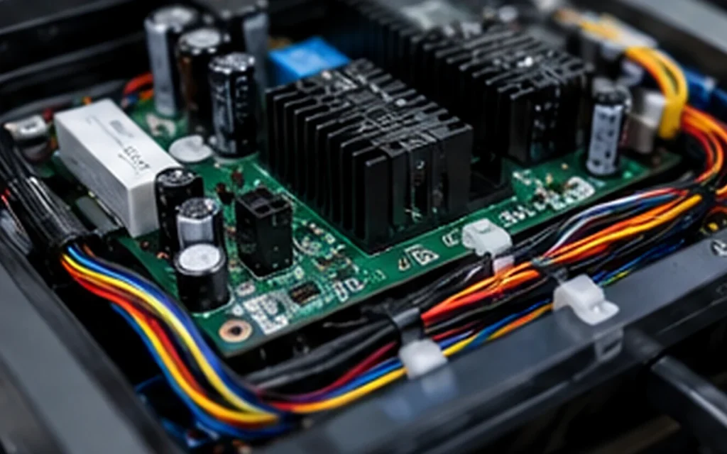
Electronic devices often have limited internal space. The harness must fit around PCBs, batteries, displays, heat sinks, screw bosses, brackets, fans, speakers and plastic clips. If the harness is too stiff, too long or routed poorly, it may block assembly or become pinched when the enclosure closes.
Buyers should check bend radius, cable length tolerance, connector exit direction, enclosure clearance, screw boss interference, heat source distance, sharp edge protection, assembly sequence, service access and cable movement noise. A wire trapped under a plastic housing can create insulation damage and field failure.
Avoiding Pinch and Assembly Damage
During final assembly, wires may be pinched by plastic housings, metal covers, screws, hinges, clips, battery compartments, display frames, heat sinks and fan brackets. This is especially common when the harness drawing does not show the routing path clearly.
Routing guides, cable clips, adhesive anchors, sleeving, labels, foam pads and assembly drawings can reduce production variation. For high-volume electronics, even a small assembly mistake can become expensive if repeated across thousands of units.
Step 6: Strain Relief Crimp Quality and Terminal Retention
Why Crimp Quality Matters
Crimp problems can cause intermittent power, heat, loose terminals and field returns. Buyers should review strip length, crimp height, conductor brush, insulation support, terminal plating, applicator condition, pull force, terminal insertion, locking confirmation and visual inspection.
A poor crimp may pass initial continuity testing but fail under vibration, heat or repeated handling. For battery, power and motor circuits, poor crimping can create heat and voltage drop. For signal circuits, it can create intermittent communication or sensor errors.
Strain Relief Options
Strain relief protects the wire near connectors and enclosure exits. Options include heat shrink, cable ties, adhesive anchors, boots, grommets, overmolding, clips, foam pads, sleeves and potting in special cases. The correct option depends on space, movement, serviceability, sealing and cost.
| Failure Point | Cause | Prevention |
|---|---|---|
| Wire breaks near connector | No strain relief | Add boot, clip or overmold |
| Terminal pulls out | Poor crimp or locking | Pull test and terminal retention check |
| Intermittent power | Loose contact | Use correct terminal and connector |
| Short circuit | Damaged insulation | Route away from sharp edges |
| Reversed polarity | Wrong pinout | Keying and 100% test |
| Connector unplugging | Vibration or weak latch | Locking connector |
Step 7: Consumer vs Industrial Electronics Design Priorities
Consumer Electronics Priorities
Consumer electronics projects often require compact structure, cost control, fast assembly, clean appearance, low voltage, safe battery routing, RoHS-related material control, consistent color coding, high-volume repeatability and packaging protection. The harness should help assembly teams work quickly without mistakes.
For consumer devices, appearance can also matter. Wires should not bulge under covers, create noise inside the enclosure or interfere with external design. Labels and color coding should support assembly without making the product look messy if the interior is visible during service.
Industrial Electronics Priorities
Industrial electronics projects usually require long-term stability, EMI resistance, wider temperature range, vibration resistance, maintenance labeling, modular replacement, terminal retention, service documentation, functional testing and traceability. The harness may need to survive cabinet vibration, electrical noise, heat near power modules or repeated field maintenance.
| Design Priority | Consumer Electronics | Industrial Electronics |
|---|---|---|
| Size | Very compact | Compact but serviceable |
| Cost | Highly sensitive | Balanced with reliability |
| EMI | Product dependent | Often critical |
| Temperature | Moderate | Wider range |
| Connector locking | Important | Very important |
| Serviceability | Lower priority | High priority |
| Documentation | Compliance-focused | Compliance plus maintenance |
Step 8: Testing and Inspection Requirements
Standard Electrical Tests
Electronic harness testing may include continuity, open circuit test, short circuit test, miswire test, polarity test, hi-pot where needed, insulation resistance, contact resistance, voltage drop, functional testing, LED/display testing, battery lead testing and signal testing. For high-volume production, 100% continuity and polarity tests are often critical because one reversed connection can damage a PCB or battery circuit.
Testing should match the application risk. A simple LED harness may require continuity and polarity testing. A shielded sensor harness may require shield continuity and functional signal checks. A power supply harness may need hi-pot, insulation resistance and voltage drop review.
Mechanical and Process Tests
Mechanical and process tests may include pull force, terminal retention, crimp height, crimp cross-section, connector mating test, bend test, vibration test, visual inspection, label check, length tolerance and packing inspection. These tests reduce field returns and improve production repeatability.
| Test | Purpose | Electronics Value |
|---|---|---|
| Continuity | Confirms circuit path | Prevents open circuits |
| Miswire test | Checks pinout | Prevents wrong function |
| Polarity test | Confirms positive/negative | Protects battery and PCB |
| Hi-pot | Checks insulation withstand | Supports safety circuits |
| Pull force | Confirms crimp strength | Reduces field returns |
| Shield continuity | Confirms EMI path | Supports signal quality |
| Functional test | Simulates real device use | Catches hidden failures |
Step 9: Compliance and Documentation
RoHS REACH and Material Control
For consumer and industrial electronics, buyers may request RoHS documentation, REACH declaration, halogen-free declaration where needed, conflict minerals information where needed, material datasheets, flame-retardant wire information, UL wire style information where required, supplier declaration of conformity and batch traceability.
Compliance should be addressed before mass production. If the buyer asks for documents only after shipment, the project may face market access delays, customer approval problems or retesting costs. Material declarations and document control should be part of the RFQ stage.
EMC and Electrical Safety Considerations
The harness may affect EMI emissions, ESD sensitivity, grounding, insulation distance, creepage/clearance around connectors, shield termination, enclosure grounding and product safety test performance. EMC issues are rarely caused by one component only; harness routing, grounding and cable structure can influence the final product result.
Supplier Documentation Package
A complete supplier package may include drawing, BOM, pinout, wire color table, connector datasheets, cable datasheets, inspection report, test report, first article inspection, certificate of conformity, traceability record, packing photo, revision history and engineering change record. These documents support approval, maintenance and future repeat orders.
Step 10: Supplier Selection and RFQ Checklist
What a Reliable Electronic Wire Harness Supplier Should Provide
A capable supplier should support connector sourcing, small-pitch crimping, wire cutting, stripping, crimping, soldering where needed, IDC assembly, FFC/FPC support where needed, heat shrink, sleeving, shield termination, continuity testing, hi-pot testing, pull force testing, visual inspection, labeling, traceability, prototype support, mass production and engineering review.
For serious OEM projects, buyers should review actual production control, not only sales claims. A qualified Electronic Wire Harness factory should be able to show incoming inspection, crimping control, terminal insertion checks, harness boards, test fixtures, label control, packing control and traceability records. In electronic products, repeatability is just as important as the first sample.
Buyer RFQ Checklist
| RFQ Item | Why It Matters | Buyer Requirement |
|---|---|---|
| Product type | Controls design priority | Consumer device, industrial controller, display, power module or sensor system |
| Voltage/current | Controls wire and connector rating | Operating current, peak current and safety margin |
| Connector part numbers | Controls compatibility | Brand, series, pitch, terminal and housing |
| Pinout | Controls function and polarity | Pin table, color code and keying requirement |
| Shielding | Controls EMI performance | Shield type, drain wire and grounding point |
| Enclosure space | Controls routing | Bend radius, exit direction and assembly path |
| Compliance | Controls market approval | RoHS, REACH, UL style, flame or customer-specific documents |
Common Buyer Mistakes
Mistake 1: Choosing Connectors Only by Pin Count
Pin count does not guarantee fit, current capacity, locking strength or assembly convenience. Buyers should review pitch, lock, orientation, current rating, mating height and terminal compatibility before approving a connector.
Mistake 2: Ignoring EMI in Signal Harnesses
Sensor noise, display flicker, data errors and EMC test failure can appear when shielding and routing are ignored. Signal harnesses should be designed with twisting, shielding, grounding and route separation where needed.
Mistake 3: No Polarity Protection
Battery and power harnesses can damage PCBs if polarity is reversed. Keyed connectors, color coding, polarity labels and 100% electrical testing can reduce this risk.
Mistake 4: Weak Strain Relief
Wires often fail near connector exits or enclosure openings. Clips, boots, heat shrink, overmolding or routing supports can reduce stress and improve service life.
Mistake 5: Buying Only by Unit Price
A cheaper harness may create field returns, assembly rework, failed tests and production delays. Buyers should compare total quality cost, not only price per cable assembly.
Industry Trends in Electronic Wire Harness Design
Devices Are Becoming Smaller and More Integrated
Smaller electronic products increase demand for compact harness routing, small-pitch connectors, thinner wires and more careful enclosure design. This makes early harness engineering more important.
More Electronics Need EMI-Aware Harness Design
Wireless modules, switching power supplies, high-speed signals and compact PCB layouts increase EMI risk. Harness shielding and routing are becoming more important in both consumer and industrial electronics.
Battery-Powered Products Need Safer Harnesses
Battery leads require polarity control, insulation, heat management, short-circuit prevention and connector reliability. A battery harness mistake can create serious product failure and customer complaints.
Industrial Electronics Demand Better Traceability
Industrial buyers increasingly expect revision control, test records, label consistency, supplier declarations and serviceable harness structures. Traceability helps maintenance teams manage future repairs and repeat orders.
Automation Improves Harness Inspection
Vision inspection, automated test fixtures, barcode labels and digital records are improving harness quality control. These tools reduce human error and strengthen batch consistency.
Final Recommendation: Design the Electronic Harness as Part of the Product
An Electronic Wire Harness should not be treated as a late-stage accessory. It should be designed together with the PCB, enclosure, power system, sensor layout, display position, EMI plan and assembly process. When the harness is considered early, the product is easier to assemble, safer to test and more reliable in the field.
Before requesting an Electronic Wire Harness quote, prepare your product type, voltage/current, connector part numbers, pinout, wire gauge, cable length, shielding requirement, enclosure space, compliance needs, test requirements, prototype quantity and annual volume. A professional custom Electronic Wire Harness manufacturer can help design a compact, reliable and production-ready cable assembly for consumer and industrial electronics.
Frequently Asked Questions About Electronic Wire Harnesses
1. What is an Electronic Wire Harness?
An Electronic Wire Harness is a pre-assembled wiring system used to connect PCBs, sensors, batteries, displays, fans, switches, power supplies, LED modules, motors and control boards inside electronic equipment. It includes wires, terminals, connectors, labels, sleeves, shielding and protective parts. A well-designed electronic harness helps improve assembly speed, pinout accuracy, signal stability, electrical safety, compliance support and long-term product reliability.
2. How is an Electronic Wire Harness different from a standard wire harness?
An Electronic Wire Harness usually requires smaller connectors, compact routing, PCB compatibility, signal integrity, EMI control and high-volume consistency. Standard wire harnesses may focus more on larger equipment routing, power distribution or mechanical environment. Electronic harnesses must often fit inside tight enclosures, connect small-pitch PCB headers, protect sensitive signals, prevent polarity mistakes and support fast production assembly.
3. What connectors are commonly used in electronic wire harnesses?
Common connectors for electronic wire harnesses include small-pitch PCB connectors, JST-type connectors, Molex-type connectors, TE-style board connectors, IDC connectors, FFC/FPC cables, battery connectors, display connectors, fan connectors, sensor connectors and external interface connectors. The correct connector should be selected by pitch, current rating, voltage rating, mating height, locking design, orientation, terminal retention, assembly method and service requirements.
4. How do you prevent EMI problems in electronic harness design?
EMI problems can be reduced by using shielded cable, twisted pairs, proper grounding, controlled shield termination, route separation between power and signal wires, connector shielding and layout review based on signal sensitivity. Sensitive sensor, display, audio, encoder and communication lines should not be routed carelessly beside noisy power, motor or switching circuits. EMI prevention should be designed before prototype testing, not only after EMC failure.
5. How do I choose an Electronic Wire Harness supplier?
Choose an Electronic Wire Harness supplier with small-pitch crimping capability, connector sourcing support, PCB interface understanding, shielding experience, test fixtures, traceability, prototype support and mass production control. A reliable supplier should ask about product type, connector part numbers, pinout, voltage/current, signal type, wire gauge, cable length, enclosure space, shielding requirement, compliance documents, test requirements, prototype quantity and annual volume before recommending a design.
References
- IPC/WHMA-A-620F Requirements and Acceptance for Cable and Wire Harness Assemblies, Author: IPC and WHMA Technical Committee, Institution: IPC International and WHMA, Source: Cable and Wire Harness Assembly Standard.
- UL 758 Appliance Wiring Material, Author: UL Standards Technical Committee, Institution: UL Standards & Engagement, Source: Appliance Wiring Material Standard.
- Directive 2011/65/EU on the Restriction of Hazardous Substances in Electrical and Electronic Equipment, Author: European Parliament and Council Contributors, Institution: European Union, Source: RoHS Directive.
- Directive 2014/30/EU on Electromagnetic Compatibility, Author: European Parliament and Council Contributors, Institution: European Union, Source: EMC Directive.
- IEC 62368-1 Audio/Video, Information and Communication Technology Equipment – Safety Requirements, Author: IEC Technical Committee Contributors, Institution: International Electrotechnical Commission, Source: Product Safety Standard.
- IEC 61000 Electromagnetic Compatibility Series, Author: IEC Technical Committee Contributors, Institution: International Electrotechnical Commission, Source: EMC Testing Reference.
- Electronic Packaging and Interconnection Handbook, Author: Electronics Manufacturing Technical Contributors, Institution: Electronics Manufacturing and Design Publications, Source: Electronics Interconnection Reference.
- Quality Management Systems Requirements, Author: ISO Technical Committee Contributors, Institution: International Organization for Standardization, Source: Quality Management Reference.
How Buyers Should Design and Source Electronic Wire Harnesses
How should buyers start an Electronic Wire Harness project?
Buyers should start by defining product function, PCB interface, voltage/current, signal type, connector pitch, pinout, enclosure space, shielding requirement, assembly process and compliance needs. Harness design should begin before enclosure and PCB layout are fully locked.
Why does PCB connector selection matter so much?
PCB connector selection affects mating accuracy, assembly speed, current capacity, locking strength, polarity control and rework risk. A small connector may save space but increase production difficulty if pitch, orientation or terminal retention is poorly selected.
What option works best for consumer electronics?
Consumer electronics usually need compact, cost-controlled and easy-to-assemble harnesses with stable pinout, clean routing, safe battery leads, reliable PCB connectors and material compliance documentation.
What option works best for industrial electronics?
Industrial electronics usually need stronger connector locking, EMI shielding, vibration resistance, temperature tolerance, service labels, traceability and functional testing because the product may operate for many years in factory or equipment environments.
Consideration: What creates the highest electronics harness risk?
The highest risks come from wrong pinout, reversed polarity, connector looseness, weak strain relief, poor EMI shielding, small-pitch assembly errors, insufficient testing and missing compliance documents.
Recommendation
Select the harness as part of the full electronic product architecture. Confirm connector compatibility, wire gauge, shielding, routing, strain relief, testing and documentation before mass production. The lowest harness price is rarely the lowest total product cost.
Send your supplier the product function, PCB connector part numbers, pinout, voltage/current, signal type, enclosure space, shielding requirement, compliance needs and annual volume. A qualified Electronic Wire Harness supplier can recommend a safer, cleaner and more production-ready design.