An electric vehicle prototype completes initial road testing successfully. Battery output is stable, the inverter runs, the motor responds, and the charging system works. After vibration testing and repeated charging cycles, issues begin to appear: connector heating near the PDU, intermittent HVIL alarms, charging interruption in wet conditions, inverter noise, cracked protective sleeves near the underbody and insulation wear close to a battery pack bracket. The root cause is not one single component. The cables, connectors and protection strategy were not selected as one integrated system.
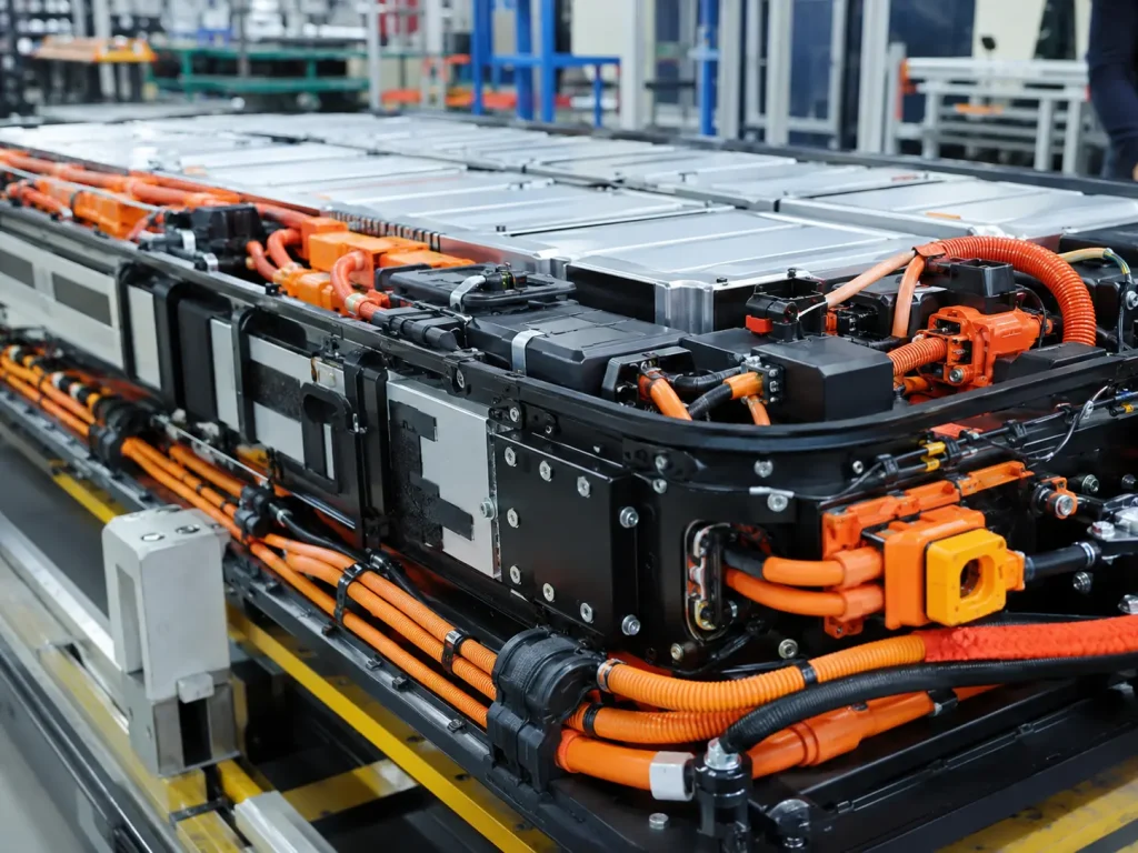
This is why an Electric Vehicle Wiring Harness is a safety-critical energy and signal pathway. Cables, connectors and protection materials must be selected together because voltage, current, heat, vibration, water, abrasion, EMI and service access all affect final harness reliability. A good EV harness is not judged only by whether it powers the vehicle during a short test. It must remain safe, traceable and stable through production, charging, driving, service and environmental exposure.
Why Cable Connector and Protection Selection Determines EV Harness Reliability
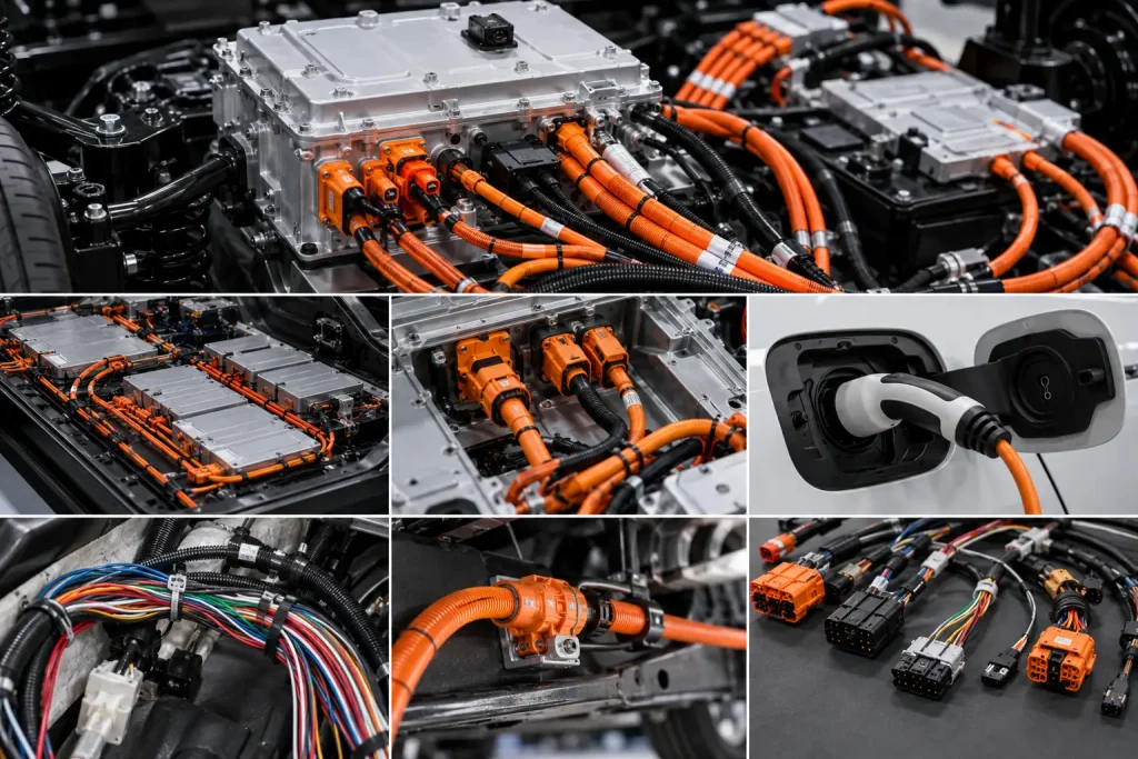
EV wiring harness selection is different from ordinary low-voltage cable sourcing. A buyer cannot simply ask for cable length, connector type and unit price. High voltage EV circuits may carry traction power, fast-charging current, inverter current, motor phase output, auxiliary high-voltage loads, BMS signals and communication circuits. Each circuit has different insulation, heat, shielding, connector and protection needs.
For buyers already reviewing high voltage EV wiring harness design, the next decision is more practical: which cable material, connector system and protection method should be used in each EV area? Battery pack routes need compact protection and insulation control. Underbody routes need abrasion and water protection. Inverter and motor controller routes need shielding and grounding. Charging inlet routes need sealing, mating-cycle stability and service safety.
| Selection Area | Main EV Risk | Buyer Should Confirm | Supplier Proof |
|---|---|---|---|
| High voltage cable | Heat and insulation failure | Voltage rating, current load, cross-section | Cable datasheet and test record |
| Connector system | Heating or unsafe disconnect | Current rating, HVIL, IP rating, locking | Connector datasheet and mating test |
| Shielding | EMI and inverter noise | Shield coverage and termination | Shield continuity record |
| Cable jacket | Aging and damage | Temperature, oil, abrasion resistance | Material datasheet |
| Protection sleeve | Underbody or battery pack wear | Sleeve material, routing, fixing | Harness drawing and sample review |
| Sealing | Water ingress | IP rating and seal structure | Seal test or connector report |
| Routing | Bend or vibration damage | Bend radius, clamp spacing, clearance | 2D/3D routing drawing |
| Traceability | Recall and batch risk | Material lot, batch, test data | Inspection and traceability record |
What Cables Are Used in Electric Vehicle Wiring Harnesses?
High Voltage Power Cables
High voltage power cables are used for battery pack output, PDU connection, inverter input, motor phase output, charging circuits, onboard charger connection and DC-DC converter circuits. These cables must carry high current while maintaining insulation safety and thermal stability. They often need visible high-voltage identification, suitable conductor cross-section, compatible terminals and strong route protection.
Design considerations include system voltage, maximum voltage, continuous current, peak current, cable cross-section, insulation material, orange jacket, temperature rating, flexibility, cable length, route clearance, voltage drop, thermal derating and connector compatibility. A cable may appear suitable by conductor size, but fail in real operation if its jacket, bend radius, terminal interface or routing protection is wrong.
Low Voltage Signal and Control Cables
Low voltage cables connect BMS, VCU, sensors, relays, HVIL, thermal management components, temperature sensors, pressure sensors, current sensors and communication circuits. These cables may carry less current, but they are critical for safety monitoring, battery control, vehicle diagnostics and charging logic.
Signal cables should be selected by pinout accuracy, route separation, shielding requirement, connector locking, service access and functional test needs. A low-voltage signal fault can trigger high-voltage disable, charging interruption, thermal management alarms or battery pack diagnostic errors.
Communication and Shielded Cables
EV systems may use CAN, LIN, Ethernet, charging communication, resolver signals, encoder signals and BMS signal lines. These communication cables should be protected from EMI, vibration, moisture and routing confusion. Shielding and grounding are especially important where communication cables run near high-current switching circuits, inverter cables or motor phase cables.
| Cable Type | Common EV Use | Main Design Focus | Buyer Risk |
|---|---|---|---|
| High voltage power cable | Battery, PDU, inverter, OBC | Voltage/current and insulation | Heating or insulation failure |
| Motor phase cable | Inverter to motor | Shielding, vibration, heat | EMI and thermal stress |
| Charging cable harness | Charging inlet to OBC/PDU | Sealing, current, mating cycles | Water ingress or charging fault |
| BMS signal cable | Battery monitoring | Signal integrity and routing | Incorrect sensing |
| HVIL cable | Safety interlock loop | Continuity and connector sequence | False fault or unsafe service |
| Shielded communication cable | CAN, Ethernet, resolver | Shielding and grounding | Data error or EMC issue |
| Grounding cable | Bonding and safety | Low resistance and secure fixing | Poor safety path |
Step 1: Define Voltage Current and Cable Cross-Section
How Voltage Platform Controls Cable Selection
EV platforms may use different voltage levels depending on vehicle type, battery system, charging target and powertrain design. Higher voltage platforms require stronger insulation awareness, connector voltage rating, creepage and clearance review, hi-pot testing and service safety planning. Voltage class should be defined before cable and connector selection begins.
Buyers should define nominal voltage, maximum voltage, transient conditions, safety margin, connector voltage rating, insulation resistance requirement, hi-pot test requirement, cable color identification and service safety needs. Without this information, the supplier cannot responsibly recommend cable insulation, connector family or test plan.
Current Load and Temperature Rise
Current determines cable size and heat behavior. Buyers should consider continuous current, peak current, charge current, discharge current, duty cycle, ambient temperature, bundle condition, route near hot components, terminal quality and connector derating. Heating may happen at the conductor, terminal, connector interface or mounting location.
| Design Factor | Why It Matters | Buyer Check |
|---|---|---|
| Continuous current | Controls long-term heating | Confirm drive and charging load |
| Peak current | Supports acceleration or transient load | Define duration and frequency |
| Cable cross-section | Controls resistance and voltage drop | Confirm by calculation and test |
| Contact resistance | Controls local heating | Request contact resistance check |
| Ambient temperature | Affects derating | Review routing environment |
| Bundle condition | Affects heat dissipation | Avoid over-packed cable routes |
| Terminal quality | Affects interface heat | Inspect crimp or lug process |
Step 2: Choose Insulation Jacket and Orange Identification
High Voltage Cable Insulation Requirements
High voltage cable insulation must match voltage, temperature, aging, abrasion, chemical exposure and route condition. Common material directions may include XLPE, cross-linked polyolefin, silicone, TPE, TPU and FEP/PTFE where special conditions apply. The best choice depends on EV platform, packaging space, heat exposure, flexibility, abrasion risk and cost target.
Buyers should check voltage rating, temperature rating, flame resistance, abrasion resistance, oil resistance, flexibility, aging behavior, cut resistance and environmental exposure. A cable that works in a protected battery pack cavity may not be suitable for underbody routing. A cable that handles temperature may not have enough flexibility for tight routing.
Why Orange Cable Identification Matters
Orange high-voltage cables help technicians, assembly workers and service teams recognize high voltage circuits quickly. This supports visual safety control during assembly, maintenance and emergency response. However, orange color does not replace proper insulation, connector locking, HVIL design, hi-pot testing, service procedure or technician training.
Buyer risks include wrong cable color, weak labels, mixed HV/LV routing, service confusion and emergency-response difficulty. Identification should be supported by durable labels, correct routing, approved drawings and service documentation.
Step 3: Select EV High Voltage Connectors
Voltage Current IP Rating and Touch Protection
EV high voltage connectors must be selected by rated voltage, rated current, temperature rating, contact resistance, IP sealing, mating cycles, terminal system, connector coding, keying, touch protection, finger-safe structure, secondary locking, cable exit direction, service access, vibration resistance and pull-out force.
A connector that is electrically rated may still fail if the seal is weak, the locking feature is not suitable for vibration, the cable exit direction creates stress, or the terminal process is unstable. Connector selection must consider electrical safety, mechanical retention, environmental sealing and service handling together.
HVIL Connector Design
HVIL detects connector disconnection or improper mating in high-voltage systems. It supports safer operation and service by helping the vehicle monitor whether high-voltage connectors are fully engaged. A poor HVIL design can cause false alarms, charging interruption, vehicle disabled status or unsafe service risk.
| Connector Feature | Function | Buyer Benefit |
|---|---|---|
| HVIL | Detects connector status | Supports safety monitoring |
| Secondary lock | Prevents accidental release | Reduces vibration loosening |
| IP seal | Prevents water and dust ingress | Supports underbody and charging use |
| Touch protection | Reduces accidental contact risk | Improves service safety |
| Keying/coding | Prevents wrong mating | Reduces assembly mistakes |
| Shield termination | Supports EMI control | Improves powertrain stability |
Step 4: Select Protection Sleeves and Routing Materials
Why Harness Protection Is More Than Cosmetic
Protection sleeves, conduits, tapes, grommets and clamps protect cables from abrasion, vibration, heat, water, dust, chemicals, sharp edges and service handling. In EV projects, protection is not only about making the harness look organized. It helps prevent insulation damage, connector stress, false faults and long-term reliability problems.
Protection options include corrugated tube, braided sleeve, heat shrink, glass fiber sleeve, silicone sleeve, abrasion-resistant tape, metal conduit, rubber grommet, cable clamp, edge guard, protective boot and strain relief. The correct choice depends on route, heat, vibration, water, service access and available space.
Protection Material Selection by EV Area
| EV Area | Main Threat | Protection Direction |
|---|---|---|
| Battery pack | Heat, abrasion, compact routing | Heat-resistant sleeve and controlled fixing |
| Underbody | Water, stone impact, abrasion | Corrugated tube, conduit, strong clamps |
| Motor/inverter area | Heat and EMI | Heat protection and shielding |
| Charging inlet | Water, mating cycles, handling | Sealed connector and strain relief |
| PDU area | Service access and vibration | Secure routing and connector locking |
| Cabin low-voltage route | Serviceability | Labels, sleeves and route separation |
Step 5: Shielding Grounding and EMI Control
Why EMI Is a Major EV Harness Risk
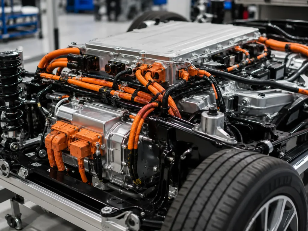
EV systems include inverters, motors, high-current switching, OBCs, DC-DC converters and fast charging modules. These systems can create noise that affects BMS, sensors, communication and vehicle control. EMI symptoms may include inverter noise, CAN communication errors, BMS instability, charging communication failure, sensor malfunction, radio interference, EMC test failure and unexpected fault codes.
EMI control should be planned early because routing, connector choice and shielding termination are difficult to correct after vehicle packaging is frozen. A cable can be shielded in name, but still perform poorly if the shield is not terminated correctly.
Shielding and Grounding Strategy
Design focus should include braid shield, foil shield, shield coverage, 360-degree termination, metal connector shell, grounding point, shield continuity, route separation, avoiding long parallel HV/LV runs, twisted pairs for communication, ground loop review and connector-level shield termination. Buyers should request shield continuity records for critical shielded cable assemblies.
Step 6: Sealing Waterproofing and Environmental Protection
EV Harness Exposure Conditions
EV wiring harnesses may face rain, underbody splash, road salt, dust, temperature cycling, battery pack condensation, cleaning water, mud and vibration. This means connector sealing, cable jacket material and route protection must match real vehicle exposure.
Buyers should check IP rating, seal material, connector gasket, cable gland, overmolding, drainage route, water-trap risk, salt-spray requirement, thermal cycling, installation angle and service handling. Waterproof performance should be considered at connector interfaces, cable exits, grommet passages and underbody fixing points.
Charging Inlet and Underbody Risks
Charging ports and underbody harnesses are especially exposed. Common risks include water ingress, seal compression loss, connector contamination, cable pulling, road debris, clamp failure, corrosion and false charging errors. A charging inlet harness should support repeated mating, water protection, current rating and service safety.
Step 7: Battery Pack Wiring Harness Protection
Internal Battery Pack Cable Routing
Inside battery packs, harnesses may connect cells, modules, BMS boards, temperature sensors, voltage sampling circuits, current sensors, cooling components and safety devices. Pack-level routing is compact, so wire protection, insulation clearance, fixing method and label clarity are important.
Design focus should include compact routing, insulation resistance, abrasion protection, heat resistance, BMS signal stability, cell module movement, service access, labeling, short-circuit prevention, flame-retardant material and pack assembly process. A small routing mistake inside the pack can create high rework cost.
High Voltage and BMS Signal Coexistence
High voltage power cables and BMS signal wires should be routed carefully to avoid noise, abrasion and service confusion. Signal wires should be separated from high-current paths where practical, and protective materials should prevent rubbing against module brackets, busbar covers and enclosure edges.
Step 8: Testing and Validation for Cables Connectors and Protection
Electrical Tests
Common electrical tests include continuity, polarity, open/short testing, hi-pot, insulation resistance, contact resistance, voltage drop, shield continuity, HVIL continuity, functional testing and leakage current evaluation where required. Critical harnesses should have traceable records by batch, material lot and drawing revision.
Mechanical and Environmental Tests
Mechanical and environmental tests may include pull force, crimp cross-section, terminal retention, connector mating, vibration, thermal cycling, temperature rise, waterproof testing, salt spray where relevant, abrasion testing, flame behavior, bend testing, aging testing, visual inspection and label inspection.
| Test | What It Checks | Buyer Value |
|---|---|---|
| Hi-pot | Insulation withstand | Supports HV safety |
| Insulation resistance | Leakage risk | Reduces shock/short risk |
| Contact resistance | Terminal quality | Prevents connector heating |
| HVIL continuity | Safety loop status | Reduces false faults |
| Shield continuity | EMI path | Supports EMC performance |
| Temperature rise | Current path validation | Reduces thermal risk |
| Waterproof test | Seal performance | Supports underbody/charging use |
| Vibration test | Connector and route stability | Reduces field failure |
Step 9: Standards Documentation and Compliance
Safety and Engineering References
EV harness projects may reference ISO 6469 series, ISO 21498, ISO 20076, UN Regulation No. 100, ISO 26262 where functional safety applies, IATF 16949 where automotive quality management is required, RoHS/REACH material declarations and customer-specific EV harness standards. These references help buyers define electrical safety, connector testing, system requirements, quality management and material compliance expectations.
The harness alone does not certify the full vehicle. It supports system-level safety and compliance, but the complete battery system, inverter, motor controller, charger, PDU, BMS, enclosure and vehicle platform must be validated together.
Supplier Documentation Package
A complete supplier documentation package may include harness drawing, cable datasheets, connector datasheets, terminal datasheets, protection material datasheets, BOM, pinout table, HVIL diagram, shielding diagram, grounding plan, routing drawing, crimp specification, hi-pot record, insulation resistance record, contact resistance record, shield continuity record, temperature-rise record, waterproof test record, FAI, PPAP where required, traceability records, packing photos, revision history and ECO records.
Step 10: Supplier Selection and RFQ Checklist
What an Electric Vehicle Wiring Harness Supplier Should Provide
A qualified supplier should provide high-voltage cable processing, EV connector assembly, shielded cable termination, HVIL loop assembly, crimping and lug processing, high-current terminal control, insulation testing, hi-pot testing, contact resistance testing, shield continuity testing, temperature-rise support, protection sleeve selection, battery pack routing support, underbody protection experience, automotive traceability, prototype support, mass production capacity and failure analysis.
A reliable Electric Vehicle Wiring Harness manufacturer should not only supply cables and connectors. It should help buyers review application risk, route conditions, connector safety, shielding, testing, traceability and production repeatability before mass production.
Buyer RFQ Checklist
Before requesting a quote, buyers should prepare vehicle type, voltage platform, continuous current, peak current, battery pack layout, PDU position, inverter position, motor controller position, OBC/DC-DC position, charging inlet requirement, cable length, cable cross-section target, connector part numbers, HVIL requirement, shielding requirement, protection sleeve requirement, IP rating, temperature range, routing drawing, bend radius, vibration requirement, testing requirement, documentation requirement, prototype quantity, annual volume and delivery schedule. Buyers can contact an Electric Vehicle Wiring Harness supplier with these details to reduce quoting errors and design risk.
| RFQ Item | Why It Matters | Buyer Requirement |
|---|---|---|
| Voltage platform | Controls insulation and connector rating | Nominal and maximum voltage |
| Current load | Controls cable size and heating | Continuous current, peak current and charging current |
| Connector part numbers | Controls compatibility and lead time | HV connector, terminal, seal and HVIL details |
| Protection requirement | Controls route durability | Sleeve, conduit, clamp, grommet or boot requirement |
| Shielding requirement | Controls EMI performance | Shield type, termination and grounding method |
| Testing requirement | Controls quality confidence | Hi-pot, insulation, contact resistance, HVIL, shield and waterproof tests |
Common Buyer Mistakes
Mistake 1: Choosing Cable Only by Current Rating
A cable may carry the required current but still fail because of bend radius, connector heat, insulation aging, water exposure or route damage. Buyers should check voltage, current, thermal behavior, connector system, jacket material and physical route together.
Mistake 2: Ignoring Connector Contact Resistance
Local overheating often starts at the terminal or connector interface. Buyers should validate terminal selection, crimping process, torque control, contact resistance and temperature-rise behavior for high-current circuits.
Mistake 3: Weak Harness Protection in Underbody Areas
Underbody routes may face water, stone impact, vibration, road salt and abrasion. Weak sleeves, poor clamps or exposed cable exits can lead to insulation damage and vehicle faults. Suitable sleeves, conduit, clamps and waterproof connectors should be planned early.
Mistake 4: Poor Shield Termination
Shielded cable will not solve EMI problems if the shield is not terminated correctly. Buyers should review shield coverage, connector termination, grounding plan and shield continuity records.
Mistake 5: Buying Only by Lowest Price
Low price can hide material substitution, incomplete testing, weak traceability, poor sealing or unstable crimp quality. In EV applications, hidden cost may appear as overheating, water ingress, HVIL faults, EMI problems, vehicle downtime and recall exposure.
Industry Trends in EV Cable Connector and Protection Design
Higher Voltage Platforms Need Better Insulation and Connector Control
Higher-performance EV platforms increase demand for safer insulation, connector validation, creepage and clearance awareness and stronger test documentation. Buyers should confirm voltage rating, insulation resistance and hi-pot test requirements early.
Fast Charging Raises Current and Thermal Requirements
Charging cable assemblies need stronger current capacity, connector stability and temperature-rise review. Charging inlet harnesses must also consider repeated mating, water exposure and user handling.
Battery Pack Integration Requires Compact and Safer Routing
Battery pack harnesses need better protection, labels, compact routing and BMS coexistence planning. A small routing error inside a pack can become expensive during production or service.
Underbody Harness Protection Is Becoming More Important
Road debris, water, salt and vibration require stronger protection strategy. Underbody harnesses should be reviewed for clamps, sleeves, grommets, bend radius and connector sealing.
Buyers Demand More Test Data and Traceability
EV OEMs increasingly request inspection records, material traceability, FAI, PPAP, batch data and test reports. Traceability helps manage quality issues and repeat production.
Final Recommendation: Select EV Harness Components as One System
Cables, connectors and protection materials should be selected as one integrated Electric Vehicle Wiring Harness system. High voltage power circuits require voltage rating, current capacity, insulation and temperature-rise control. Inverter and motor routes require shielding and grounding. Charging circuits require sealing and mating-cycle reliability. Battery pack routes require compact protection, label clarity and insulation safety. Underbody routes require abrasion, water and impact protection.
Before requesting an Electric Vehicle Wiring Harness quote, prepare your voltage platform, current load, battery/PDU/inverter/OBC layout, cable length, connector part numbers, HVIL requirement, shielding requirement, protection sleeve requirement, IP rating, routing drawing, testing needs and annual volume. A professional Electric Vehicle Wiring Harness supplier can help select cables, connectors and protection materials that reduce overheating, EMI faults, water ingress and long-term vehicle reliability risks.
Frequently Asked Questions About EV Wiring Harness Cable Connector and Protection Selection
1. What cables are used in Electric Vehicle Wiring Harnesses?
Electric Vehicle Wiring Harnesses may use high voltage power cables, motor phase cables, charging cable harnesses, BMS signal wires, HVIL wires, shielded communication cables, low voltage control cables and grounding cables. High voltage cables are usually used for battery, PDU, inverter, motor, OBC and charging circuits, while low voltage and communication cables support sensing, safety monitoring, diagnostics and control functions.
2. How do I choose connectors for EV wiring harnesses?
Choose EV wiring harness connectors by rated voltage, rated current, IP rating, HVIL function, touch protection, connector locking, contact resistance, mating cycles, shield termination, vibration resistance, cable exit direction and service access. A connector should not be selected only because it fits the cable. It must support electrical safety, thermal stability, sealing, mechanical retention and correct mating in the real vehicle environment.
3. Why do EV wiring harnesses need protection sleeves?
EV wiring harnesses need protection sleeves because cables may face abrasion, heat, vibration, water exposure, stone impact, sharp-edge damage, battery pack movement and service handling. Protection sleeves, conduits, tapes, grommets and clamps help prevent insulation wear, connector stress, routing damage and long-term reliability problems. The correct protection material depends on whether the harness is inside the battery pack, underbody, motor area, charging inlet or cabin route.
4. What tests should EV cables and connectors pass?
EV cables and connectors may need continuity testing, hi-pot testing, insulation resistance testing, contact resistance testing, shield continuity testing, HVIL continuity testing, temperature-rise testing, waterproof testing, vibration testing, terminal retention testing and visual inspection. The exact test plan depends on voltage platform, current load, connector type, route exposure, shielding requirement and customer specification. Critical EV harnesses should have traceable test records.
5. How do I choose an Electric Vehicle Wiring Harness supplier?
Choose an Electric Vehicle Wiring Harness supplier with high-voltage cable processing capability, EV connector assembly experience, shielded cable termination, HVIL loop assembly, protection sleeve selection, contact resistance testing, hi-pot testing, insulation resistance testing, waterproofing knowledge, automotive traceability, prototype support and mass production capacity. A reliable supplier should ask for voltage, current, routing, connector, shielding, protection and testing requirements before quoting.
References
- ISO 6469-3:2021 Electrically Propelled Road Vehicles – Safety Specifications – Electrical Safety, Author: ISO Technical Committee Contributors, Institution: International Organization for Standardization, Source: EV Electrical Safety Standard.
- ISO 21498-1:2021 Electrically Propelled Road Vehicles – Electrical Specifications and Tests for Voltage Class B Systems and Components, Author: ISO Technical Committee Contributors, Institution: International Organization for Standardization, Source: EV Voltage Class B System Reference.
- ISO 20076:2019 Road Vehicles – Test Methods and Performance Requirements for Voltage Class B Connectors, Author: ISO Technical Committee Contributors, Institution: International Organization for Standardization, Source: EV High Voltage Connector Standard.
- UN Regulation No. 100 Uniform Provisions Concerning Electric Power Train Requirements, Author: UNECE Working Party Contributors, Institution: United Nations Economic Commission for Europe, Source: Electric Power Train Safety Regulation.
- ISO 26262 Road Vehicles – Functional Safety, Author: ISO Technical Committee Contributors, Institution: International Organization for Standardization, Source: Automotive Functional Safety Standard.
- IATF 16949 Automotive Quality Management System Standard, Author: International Automotive Task Force Contributors, Institution: International Automotive Task Force, Source: Automotive Quality Management Reference.
- Electric Vehicle High Voltage Cable and Connector Engineering Guidance, Author: Automotive Electrical Engineering Contributors, Institution: Automotive Engineering and Power Electronics Publications, Source: EV Harness Design Reference.
- Quality Management Systems Requirements, Author: ISO Technical Committee Contributors, Institution: International Organization for Standardization, Source: Quality Management Reference.
How Buyers Should Select EV Cables Connectors and Protection
How should buyers start selecting EV harness components?
Buyers should start with the vehicle architecture, voltage platform, current load, battery/PDU/inverter/OBC layout, connector system, route exposure, HVIL requirement, shielding requirement and testing plan. Cable, connector and protection choices should be made together.
Why should cables and connectors be evaluated as one system?
A good cable can still fail if the connector has high contact resistance, poor sealing or weak locking. A good connector can still fail if cable routing, protection sleeve or bend radius is wrong. EV harness reliability depends on the complete electrical and mechanical path.
What option works best for high-voltage battery and PDU routes?
For battery and PDU routes, prioritize voltage rating, cable cross-section, insulation resistance, contact resistance, terminal quality, orange identification, temperature-rise validation and secure route protection.
What option works best for inverter motor and EMI-sensitive routes?
For inverter and motor routes, prioritize shielded cable, correct shield termination, grounding strategy, vibration resistance, bend radius control, route separation and shield continuity testing.
Consideration: What creates the highest EV harness selection risk?
The highest risks come from selecting cable only by current rating, ignoring connector contact resistance, weak underbody protection, poor shield termination, insufficient waterproofing and buying only by lowest unit price.
Recommendation
Select EV harness components by safety, thermal control, EMI behavior, waterproofing, abrasion protection, service access and supplier traceability. Confirm the complete cable, connector and protection system before prototype release and mass production.
Send your supplier the voltage/current data, connector part numbers, cable route, HVIL design, shielding needs, protection sleeve requirements, IP target and test plan. A qualified Electric Vehicle Wiring Harness supplier can recommend a safer and more production-ready cable assembly.