A packaging machine or robotic assembly line is delivered to a customer factory. During factory acceptance testing, the machine runs smoothly. The PLC program looks stable, the servo axes move correctly, and the sensors respond as expected. After several weeks of production, however, problems appear: random servo alarms, unstable sensor signals, intermittent encoder feedback, broken cables inside the drag chain, oil-damaged jackets, loose connectors in the control cabinet and confusing maintenance labels.
The PLC program is not always the real problem. In many automation failures, the hidden cause is a weak Industrial Wire Harness design that does not match the machine’s real environment. Automation equipment runs under vibration, electrical noise, repeated motion, oil mist, dust, water splash, high-speed cycles and long working hours. A harness that works in a static sample may fail when installed on a moving axis or inside a noisy control system.
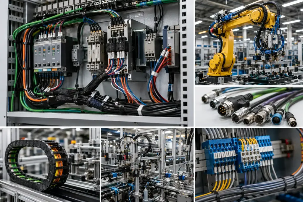
Why Industrial Wire Harness Design Matters in Automation Equipment
An Industrial Wire Harness is a critical connection system for machine builders, automation integrators and equipment OEMs. It affects machine uptime, signal stability, servo accuracy, safety circuits, commissioning speed, maintenance efficiency and long-term operating cost. A reliable harness makes machine assembly faster, reduces wiring mistakes and helps technicians replace parts correctly during service.
A professional Industrial Wire Harness manufacturer should understand both electrical performance and machine-level conditions. The supplier should ask about machine type, PLC map, servo drive model, motor model, encoder type, sensor list, communication protocol, cable route, drag chain requirement, oil exposure, IP rating, shielding requirement and test expectations before recommending a design. A supplier that only quotes wire length and connector count may miss the real automation risk.
| Selection Area | Automation Risk | Buyer Should Confirm | Supplier Proof |
|---|---|---|---|
| Servo power cable | Heating, EMI, motor fault | Current rating, shielding, grounding | Cable datasheet and test record |
| Encoder cable | Position error, servo alarm | Shielding, route separation, connector lock | Shield continuity and functional test |
| Sensor cable | False signal | Pinout, connector type, IP rating | Continuity and sensor test |
| Drag chain cable | Broken conductor | Bend radius, flex rating, jacket material | Flex cable specification |
| PLC/I/O harness | Wrong signal | Pinout, label, module mapping | 100% continuity test |
| EMI protection | Random fault | Shielding, grounding, separation | Shield structure and grounding plan |
| Traceability | Repeat order risk | Batch, drawing revision, test record | Inspection report |
What Is an Industrial Wire Harness?
Wiring Architecture Inside Automation Equipment
An Industrial Wire Harness is a pre-assembled cable and connector system used to connect control cabinets, PLC modules, I/O modules, servo drives, motors, encoders, sensors, switches, valves, actuators, HMIs, safety devices, machine vision cameras, industrial Ethernet modules and power components inside automation equipment.
Typical circuits include servo motor power cables, encoder feedback cables, sensor cables, PLC I/O harnesses, solenoid valve harnesses, industrial Ethernet cables, vision camera cables, safety circuit harnesses, emergency stop wiring, control cabinet internal wiring, drag chain dynamic cables, robot arm cable assemblies, VFD/motor cables, auxiliary power harnesses, grounding cables and bonding cables.
Where It Is Used
Industrial harnesses are used in packaging machinery, CNC equipment, robotic cells, conveyor systems, food processing machines, textile machinery, printing machines, battery production equipment, medical device production machines, electronic assembly lines, semiconductor equipment, automated warehouses, machine vision inspection systems, welding automation, injection molding automation and industrial test equipment.
Industrial Wire Harness vs Electronic Wire Harness
Industrial and electronic harnesses may look similar, but they are designed around different operating risks. Electronic harnesses usually focus on compact PCB connections, small-pitch connectors and enclosure fit. Industrial harnesses must survive machines, factories, control cabinets, motion routes, vibration, oil exposure, EMI and maintenance handling.
| Factor | Industrial Wire Harness | Electronic Wire Harness |
|---|---|---|
| Main environment | Machines, factories, control cabinets | Compact devices and PCB modules |
| Key risk | Vibration, oil, EMI, motion, downtime | PCB fit, small pitch, compact routing |
| Cable type | Power, servo, encoder, sensor, Ethernet | PCB, battery, display, sensor leads |
| Connector priority | Locking, IP rating, serviceability | Pitch, mating height, compact size |
| Testing focus | Continuity, insulation, shield, function | Pinout, polarity, PCB connection |
| Maintenance need | High | Medium or low |
Step 1: Define the Automation Equipment Architecture
Control Cabinet PLC Servo Drives and Field Devices
Machine builders should map the complete electrical structure before harness design. Important nodes include the main power input, control cabinet, PLC, remote I/O, servo drives, VFDs, servo motors, encoders, sensors, limit switches, solenoid valves, pneumatic actuators, HMI, safety relay, safety PLC, emergency stop, light curtain, machine vision camera, industrial Ethernet switch, robot controller, drag chain route and cable tray route.
Harness design depends on machine layout, motion axis count, cabinet position, moving cable route, sensor density, communication method and maintenance access. For example, a packaging machine with multiple servo axes needs different harness planning from a static inspection station. A robotic cell with repeated arm movement needs different routing from a conveyor line with distributed sensors.
Why Architecture Controls Harness Design
| Machine Area | Harness Function | Main Risk |
|---|---|---|
| Control cabinet | PLC/I/O and power distribution | Wrong labeling and maintenance errors |
| Servo axis | Power and feedback wiring | EMI, heat and vibration |
| Sensor zone | Signal detection | False signals and connector damage |
| Drag chain | Moving cable route | Conductor fatigue |
| Safety circuit | E-stop, light curtain and interlock | Safety signal interruption |
| Vision station | Camera and lighting cables | Data loss and cable movement |
Step 2: Servo Motor Power Harness Design
Current Rating Thermal Behavior and Shielding
Servo motor power harnesses must carry current while surviving machine vibration, acceleration, deceleration and repeated operation. Buyers should define servo motor power, rated current, peak current, cable length, drive model, connector model, shielding requirement, grounding method, temperature range, oil exposure, cable route, bend radius, strain relief, IP rating and motor-side vibration.
Servo power cables can also become noise sources. If they are routed too close to encoder feedback cables or sensor wires, the machine may experience false alarms, unstable motion or commissioning delays. Shielding, grounding and route separation should be planned before cabinet and machine layout are finalized.
Common Servo Harness Risks
| Servo Harness Item | Why It Matters | Buyer Check |
|---|---|---|
| Wire gauge | Prevents heat and voltage drop | Match current and length |
| Shielding | Reduces EMI | Confirm shield coverage and termination |
| Connector lock | Prevents vibration loosening | Check connector model |
| Jacket material | Resists oil and abrasion | Review material datasheet |
| Bend radius | Prevents conductor fatigue | Confirm route |
| Strain relief | Protects connector exit | Inspect boot or clamp design |
Step 3: Encoder Feedback and Signal Harness Design
Why Encoder Signal Integrity Matters
Encoder signals affect servo positioning, repeatability and motion control. A weak encoder harness can cause position loss, servo alarms, intermittent feedback, machine stops, repeatability errors, noise from motor cables, connector looseness, shield failure and tight-bend damage near the connector.
Encoder harnesses should be treated as precision signal paths. They are not ordinary low-voltage wires. A cable that passes a basic continuity test may still fail when routed near a motor cable, bent sharply near the connector or exposed to vibration. Buyers should request shield continuity testing and functional feedback checks where needed.
Shielding and Route Separation
Encoder cables should be separated from high-current motor cables where possible. Shield termination and grounding should follow the servo drive manufacturer’s recommendations. Design focus should include shielded twisted pair, low-noise cable, connector locking, stable impedance, grounding, bend radius, cable length limit, route separation, shield continuity testing and functional servo feedback testing.
Step 4: Sensor Cable and I/O Harness Design
Proximity Photoelectric Pressure and Limit Sensors
Industrial machines rely on many field devices: proximity sensors, photoelectric sensors, pressure sensors, flow sensors, temperature sensors, vacuum sensors, limit switches, magnetic switches, safety switches, load cells, barcode readers and vision triggers. These devices may carry low current, but they are essential to machine timing and safety logic.
A sensor cable failure can stop an entire line. A false signal may cause misfeeds, rejected products, unexpected pauses or safety faults. For automation buyers, sensor harness reliability is not a small detail; it directly affects machine uptime.
Sensor Connector and IP Rating
Sensor connector considerations include M8/M12 connectors, waterproof connectors, quick-disconnect cables, PVC or PU jackets, oil resistance, cable length, pinout, PNP/NPN signal type, analog or digital signal type, shielding, LED indicator visibility, labeling and replacement convenience.
| Sensor Type | Main Risk | Harness Design Focus |
|---|---|---|
| Proximity sensor | False trigger | Shielding and stable connector |
| Photoelectric sensor | Signal instability | Clean routing and correct pinout |
| Pressure sensor | Analog noise | Shielding and grounding |
| Limit switch | Broken wire | Strain relief and abrasion protection |
| Safety switch | Safety signal loss | Secure connector and test record |
| Vision trigger | Timing error | Signal integrity and route separation |
Step 5: Drag Chain and Continuous Motion Cable Assemblies
Why Ordinary Cables Fail in Moving Machines
Drag chain harnesses are used in moving axes, gantries, robot transfer units, pick-and-place machines, automatic doors, machine tool axes and high-speed automation equipment. Ordinary static cables may fail quickly in these applications because they are not designed for repeated bending and acceleration.
Common failure causes include conductor fatigue, jacket cracking, too tight bend radius, cable twisting, improper cable fill, no separation inside the chain, wrong jacket material, abrasion, repeated acceleration and connector stress. A cable break inside a drag chain may create difficult intermittent faults before complete failure appears.
Flex Cable Selection and Routing Rules
Buyers should confirm minimum bend radius, movement speed, acceleration, stroke length, cycle-life expectation, cable diameter, cable weight, jacket material, shielded or unshielded structure, chain fill ratio, cable separation, connector strain relief and installation orientation.
| Drag Chain Parameter | Why It Matters | Buyer Check |
|---|---|---|
| Bend radius | Controls fatigue | Match cable datasheet |
| Cycle life | Predicts service life | Define machine duty |
| Jacket material | Resists abrasion and oil | Choose PUR or suitable material |
| Cable diameter | Controls chain fit | Avoid overfill |
| Shield structure | Survives flexing | Use flex-rated shield |
| Connector exit | Prevents stress | Add strain relief |
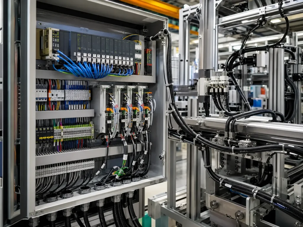
Step 6: PLC I/O and Control Cabinet Wiring Harnesses
Modular Wiring for Faster Assembly
Industrial equipment often uses PLC modules, terminal blocks, relay modules, safety relays and I/O connectors. A well-designed PLC/I/O harness can reduce assembly time, prevent wiring mistakes and make commissioning faster. Clear wire numbering, pinout mapping, terminal ferrules, cable markers, DIN-rail routing, bundle separation, service loops and module replacement logic all matter.
For repeat OEM machines, modular harnesses can improve production consistency. Instead of wiring every machine manually, pre-assembled harnesses allow technicians to install tested cable assemblies. This reduces variation between machines and makes troubleshooting easier.
Labeling and Maintenance Logic
Labels should match drawings, PLC I/O points and field device names. Maintenance technicians should be able to identify cables quickly without tracing every wire manually. Weak labeling can cause wrong replacement, long troubleshooting time, commissioning delay, unclear field wiring, wrong terminal connection and mixed cable versions.
Step 7: Industrial Ethernet Vision and Communication Cables
PROFINET EtherNet/IP EtherCAT and RS485
Modern automation systems may use PROFINET, EtherNet/IP, EtherCAT, Modbus TCP, RS485, CANopen, IO-Link, USB3 vision cables, GigE Vision, Camera Link and industrial Ethernet switches. These communication cables require stable bandwidth, shielding, connector locking, route separation and protection from mechanical stress.
Industrial Ethernet wiring should not be treated like ordinary office network cable. It may operate near servo drives, motors, VFDs, moving axes and switching power supplies. The cable structure, shield, connector and routing method should match the automation environment.
Vision System Cable Requirements
Machine vision applications require stable image data and trigger timing. Camera cables may fail if bent repeatedly or routed near noisy power cables. Buyers should check cable bandwidth, industrial camera connector, flex rating, USB/GigE/Camera Link compatibility, strain relief, shielding, lighting cable separation and trigger signal stability.
Step 8: EMI Shielding Grounding and Route Separation
Why Automation Equipment Is Noisy
Industrial equipment may include servo drives, VFDs, motors, solenoids, welders, heaters, switching power supplies and long cable routes. These components can create electrical noise that affects signals and communication. EMI symptoms include random PLC input faults, servo alarms, sensor instability, encoder errors, network dropouts, camera image noise, false safety alarms and commissioning delays.
When these faults happen, engineers may first check software or PLC logic. But the root cause can be poor cable routing, weak shielding, incorrect grounding or long parallel runs between power and signal cables.
Practical EMI Control
Practical EMI control includes separating power and signal cables, avoiding long parallel runs, using shielded cable for sensitive signals, terminating shields properly, grounding the cabinet and machine frame, using twisted pairs for communication, following drive and PLC wiring guidance, using metal cable glands where needed, documenting the grounding plan and testing shield continuity.
Step 9: Materials for Harsh Industrial Environments
Oil Water Heat Abrasion and Chemicals
Industrial harnesses may face oil mist, coolant, cleaning chemicals, dust, water splash, high temperature, metal chips and abrasion. Material selection should follow the environment. A cable jacket that works in a dry control cabinet may crack or swell near oil and coolant. A static cable may fail in a moving axis. A standard connector may not survive washdown zones.
| Environment | Material Concern | Recommended Direction |
|---|---|---|
| Oil/coolant | Jacket swelling or cracking | Oil-resistant PUR/TPE options |
| Dynamic motion | Conductor fatigue | High-flex cable |
| High heat | Insulation aging | Silicone/PTFE where suitable |
| Abrasion | Jacket damage | Braided sleeve or conduit |
| Water/dust | Connector ingress | IP-rated connectors |
| Welding area | Heat and sparks | Protective conduit and routing distance |
Step 10: Testing and Quality Control
Electrical Testing
Common electrical tests include continuity, open/short testing, miswire testing, polarity testing, hi-pot testing, insulation resistance, shield continuity, contact resistance, functional testing, network cable testing, sensor signal testing and servo feedback testing. The test plan should match the circuit type and machine risk.
A harness for static cabinet wiring may need continuity and label checks. A servo feedback cable may need shield continuity and functional signal testing. A drag chain harness may need flex-life review. A safety circuit harness should receive stricter documentation and traceability.
Mechanical and Process Testing
Mechanical and process tests may include crimp height, crimp cross-section, pull force, terminal retention, connector mating, bend testing, drag chain simulation where required, vibration testing where required, waterproof testing where required, visual inspection, label inspection, length tolerance and packing inspection.
| Test | Purpose | Automation Value |
|---|---|---|
| Continuity | Confirms circuit path | Prevents wiring errors |
| Miswire test | Confirms pinout | Reduces commissioning delay |
| Hi-pot | Checks insulation | Supports safety circuits |
| Shield continuity | Confirms EMI path | Reduces signal faults |
| Pull force | Confirms crimp strength | Reduces field failure |
| Functional test | Simulates device signal | Catches hidden faults |
| Flex test | Checks motion cable life | Reduces drag chain failure |
| Label inspection | Confirms service logic | Improves maintenance speed |
Step 11: Standards Documentation and Compliance
Machinery Electrical and Harness Workmanship References
Industrial automation projects may reference IEC 60204-1 for machine electrical equipment, NFPA 79 for industrial machinery electrical requirements, UL 508A where industrial control panels are involved, IPC/WHMA-A-620 for cable and wire harness workmanship expectations, ISO 9001 for quality management, CE-related machinery requirements where applicable, and RoHS/REACH material declarations where required.
The harness alone does not certify the machine. It supports machine-level compliance and reliability, but the complete machine, control system, safety circuits and installation must be evaluated together. Good harness documentation helps engineers, auditors and maintenance teams understand what was built, tested and shipped.
Supplier Documentation Package
A complete supplier documentation package may include harness drawing, BOM, wire list, pinout table, PLC I/O mapping, cable datasheets, connector datasheets, shielding diagram, grounding plan, labeling standard, inspection report, continuity test record, hi-pot record, insulation resistance record, shield continuity record, pull force report, first article inspection, traceability record, packing photos, revision history and engineering change record.
Step 12: Supplier Selection and RFQ Checklist
What an Industrial Wire Harness Supplier Should Provide
A reliable supplier should provide servo cable assembly, encoder cable assembly, sensor cable assembly, PLC/I/O harness assembly, industrial Ethernet cable assembly, shielded cable termination, drag chain cable experience, oil-resistant cable sourcing, connector sourcing, crimping, soldering where required, continuity testing, hi-pot testing, shield continuity testing, functional testing, labeling, traceability, prototype support, mass production and failure analysis.
Buyers who are preparing a machine program can use a custom wire harness buying guide for OEM engineers and procurement teams as a broader sourcing reference when comparing drawings, testing requirements, supplier capability, documentation, lead time and long-term production control.
Buyer RFQ Checklist
Before requesting a quote, buyers should prepare machine type, control cabinet layout, PLC/I/O map, servo drive model, motor model, encoder type, sensor list, communication protocol, cable length, cable route, drag chain requirement, bend radius, oil/water/heat exposure, connector part numbers, IP rating, shielding requirement, grounding requirement, testing requirement, documentation requirement, prototype quantity, annual volume and delivery schedule. Buyers can contact an Industrial Wire Harness supplier with these details to receive a more accurate technical recommendation.
| RFQ Item | Why It Matters | Buyer Requirement |
|---|---|---|
| Machine type | Controls environment and routing | Packaging, CNC, robot, conveyor, vision or other automation equipment |
| PLC/I/O map | Controls pinout and labels | Module mapping, signal type and wire number |
| Servo system | Controls power and feedback cables | Drive, motor, encoder and connector models |
| Drag chain route | Controls flex cable choice | Bend radius, stroke length, speed and cycle expectation |
| Environment | Controls material selection | Oil, water, dust, heat, vibration or chemicals |
| Testing | Controls quality confidence | Continuity, hi-pot, shield, signal, flex or functional tests |
Common Buyer Mistakes
Mistake 1: Treating Automation Harnesses Like Static Cables
Moving axes, gantries and drag chains require flex-rated cables. Static cables may break internally after repeated bending. Buyers should confirm bend radius, cable structure, jacket material and cycle-life expectations.
Mistake 2: Mixing Power and Signal Routes
Power cables, servo cables and VFD cables can create noise that affects sensors, encoders and networks. Buyers should separate power and signal routes, use shielding where needed and follow grounding guidance.
Mistake 3: Ignoring Oil and Coolant Exposure
Industrial equipment may expose cables to oil mist, coolant or cleaning chemicals. A weak jacket can crack, swell or harden. Oil-resistant cable materials should be selected for harsh machine environments.
Mistake 4: Weak Labeling in Control Cabinets
Unclear labels create long troubleshooting time and maintenance errors. Wire numbers, connector labels and drawing-matched identification should be part of the harness design, not an afterthought.
Mistake 5: Buying Only by Cable Price
Low unit price can hide weak materials, poor shielding, incomplete testing, short flex life or poor labels. The hidden cost may appear as machine downtime, commissioning delays, warranty claims and customer complaints.
Industry Trends in Industrial Wire Harness Design
More Machines Use Servo and Motion Control
Higher servo axis counts increase demand for reliable power and encoder harnesses. As machines become faster and more precise, harness design must support motion accuracy, EMI control and vibration resistance.
Machine Vision Requires Better Data Cable Control
Vision systems depend on stable camera data, lighting control and trigger signals. Cable bandwidth, shielding, strain relief and route protection are becoming more important in inspection and robotic automation.
Drag Chain Applications Need Longer Flex Life
Automation buyers increasingly ask for cable life, bend-radius data and dynamic routing support. The harness must match the actual motion profile rather than only the connector type.
Modular Wiring Reduces Commissioning Time
Pre-assembled PLC/I/O, sensor and cabinet harnesses can shorten machine assembly and reduce wiring variation. Modular harness design also helps repeat OEM production.
EMI Control Becomes More Important
Servo drives, VFDs, high-speed networks and industrial Ethernet make shielding and grounding more critical. Strong EMI planning reduces random machine faults and commissioning delays.
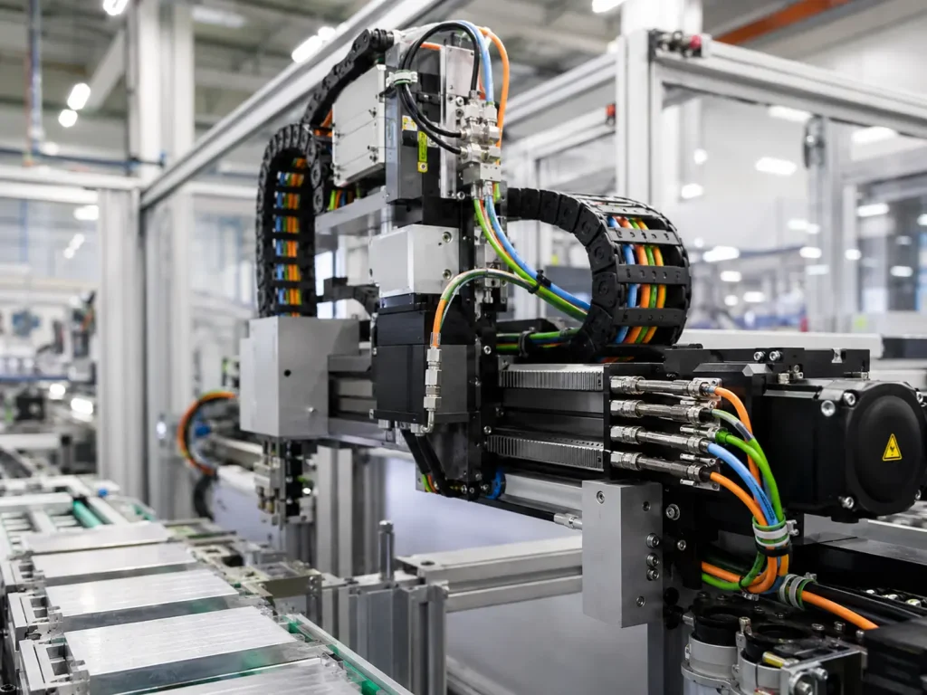
Final Recommendation: Design Industrial Harnesses Around Machine Uptime
An Industrial Wire Harness should be designed around machine function, motion type, electrical noise, environment and maintenance logic. Servo power cables need current rating, shielding, oil resistance and strain relief. Encoder cables need signal integrity and route separation. Sensor cables need correct pinout, IP rating and service labels. Drag chain cables need flex life and bend-radius control. PLC/I/O harnesses need labeling, modular replacement and 100% continuity testing.
Before approving bulk production, buyers should verify the harness drawing, cable datasheet, connector selection, route plan, shielding method, grounding logic, test requirements, labels, traceability and packing method. A professional Industrial Wire Harness supplier can help reduce commissioning problems, false alarms, cable breakage and long-term machine downtime.
Frequently Asked Questions About Industrial Wire Harnesses
1. What is an Industrial Wire Harness?
An Industrial Wire Harness is a pre-assembled wiring system used to connect control cabinets, PLC modules, servo drives, motors, encoders, sensors, valves, HMIs, safety devices, industrial Ethernet modules and field equipment in automation machinery. It organizes power, signal, feedback, communication and safety circuits into a controlled cable assembly. A well-designed Industrial Wire Harness improves machine assembly, commissioning speed, signal reliability, maintenance convenience and long-term uptime.
2. How is an Industrial Wire Harness different from a standard cable assembly?
An Industrial Wire Harness is designed for machine environments where vibration, oil, coolant, repeated motion, EMI, dust, water, labeling, serviceability and downtime risk matter. A standard cable assembly may only provide a basic electrical connection. Industrial harnesses must consider connector locking, IP rating, shielding, grounding, bend radius, drag chain compatibility, oil-resistant materials, wire numbering, machine drawings and functional testing for automation equipment.
3. What cable is best for drag chain applications?
The best cable for drag chain applications is a high-flex cable selected by bend radius, cycle-life expectation, jacket material, conductor structure, shielding design, cable diameter, movement speed and connector strain relief. Ordinary static cables may break internally after repeated bending. For moving axes, buyers should confirm the cable datasheet, chain fill ratio, installation orientation and route design before approving production.
4. How do you prevent EMI problems in industrial automation harnesses?
EMI problems can be reduced by separating power and signal routes, avoiding long parallel runs, using shielded cable for sensitive signals, terminating shields correctly, grounding the cabinet and machine frame properly, using twisted pairs for communication, following servo drive and PLC wiring guidance, and testing shield continuity. EMI prevention is especially important around servo drives, VFDs, motors, welders, switching power supplies, encoders, sensors and industrial Ethernet networks.
5. How do I choose an Industrial Wire Harness supplier?
Choose an Industrial Wire Harness supplier with experience in servo cable assembly, encoder cable assembly, sensor harnesses, PLC/I/O wiring, shielded cable termination, drag chain cable design, oil-resistant materials, functional testing, labeling, traceability and prototype-to-mass-production support. A reliable supplier should ask about machine type, electrical architecture, motion route, environment, connector models, shielding, testing requirements and annual volume before recommending a design.
References
- IPC/WHMA-A-620F Requirements and Acceptance for Cable and Wire Harness Assemblies, Author: IPC and WHMA Technical Committee, Institution: IPC International and Wiring Harness Manufacturer’s Association, Source: Cable and Wire Harness Assembly Standard.
- IEC 60204-1 Safety of Machinery – Electrical Equipment of Machines, Author: IEC Technical Committee Contributors, Institution: International Electrotechnical Commission, Source: Machinery Electrical Equipment Standard.
- NFPA 79 Electrical Standard for Industrial Machinery, Author: NFPA Technical Committee, Institution: National Fire Protection Association, Source: Industrial Machinery Electrical Standard.
- UL 508A Standard for Industrial Control Panels, Author: UL Standards Technical Committee, Institution: UL Standards & Engagement, Source: Industrial Control Panel Standard.
- ISO 9001 Quality Management Systems Requirements, Author: ISO Technical Committee Contributors, Institution: International Organization for Standardization, Source: Quality Management System Standard.
- Industrial Ethernet Installation and Cabling Guidance, Author: Industrial Automation Technical Contributors, Institution: Automation and Control Engineering Publications, Source: Industrial Network Cabling Reference.
- Servo Drive and Encoder Wiring Application Guidance, Author: Motion Control Engineering Contributors, Institution: Industrial Motion Control Publications, Source: Servo System Wiring Reference.
- Machine Vision Cable and Trigger Signal Design Guidance, Author: Vision System Engineering Contributors, Institution: Industrial Machine Vision Publications, Source: Machine Vision Integration Reference.
How Buyers Should Design Industrial Wire Harnesses for Automation Equipment
How should buyers start an Industrial Wire Harness project?
Buyers should start with the machine architecture: PLC/I/O map, servo drives, motors, encoders, sensors, communication networks, safety circuits, drag chain routes and control cabinet layout. The harness should be designed as part of the automation system, not purchased as a simple cable bundle.
Why does motion change the harness design?
Moving axes and drag chains expose cables to repeated bending, acceleration and connector stress. If the harness uses ordinary static cable, conductors may fatigue and fail internally. Flex-rated cable, correct bend radius and strain relief are essential for motion applications.
What option works best for servo and encoder systems?
Servo power cables should prioritize current rating, shielding, grounding, oil resistance and connector locking. Encoder cables should prioritize signal integrity, shield continuity, route separation and stable connector mating.
What option works best for sensor and PLC/I/O harnesses?
Sensor and PLC/I/O harnesses should prioritize correct pinout, clear labels, module mapping, continuity testing, IP-rated connectors where required and easy replacement logic for maintenance technicians.
Consideration: What creates the highest automation harness risk?
The highest risks come from treating moving cables like static cables, mixing power and signal routes, ignoring oil exposure, weak control cabinet labeling, incomplete testing and selecting suppliers only by lowest price.
Recommendation
Select the harness by machine uptime value. Confirm cable material, connector locking, shielding, grounding, drag chain compatibility, testing, labeling, documentation and supplier traceability before mass production.
Send your supplier the machine type, PLC/I/O map, servo drive model, motor model, encoder type, sensor list, communication protocol, cable route, drag chain data, environment and testing needs. A qualified Industrial Wire Harness supplier can recommend a more reliable automation cable assembly.